Air Flow Meter
Discussion


Suspect my airflow meter has given up.
Testing it it overshoots then takes ages to settle down.
It's on a 1999 450.
Nothing special going on in terms of modifications (act racing headers and racing cats).
Seems to be mucking up the mixture.
Very sooty exhaust, more thirsty than usual.
I've had a quick look around and the price of airflow meters vary wildly, obviously I don't want to risk a crap Chinese eBay version. What's the best course of action?
Yup still got it.
Bosch Part# 0280218010, was on my car for less than 1500 miles before the SC was fitted.
I'm in Taunton ... shame you didn't post this last week, I was at the Neil Garner Open Day
I could get it shipped by Hermes for less than a tenner.
Make me an offer by PM if you're interested
Bosch Part# 0280218010, was on my car for less than 1500 miles before the SC was fitted.
I'm in Taunton ... shame you didn't post this last week, I was at the Neil Garner Open Day
I could get it shipped by Hermes for less than a tenner.
Make me an offer by PM if you're interested
Edited by sgrimshaw on Monday 28th September 16:40
The Bosch and 5AM are not compatible mapping wise, so you will need a remap or specific chip if you are swapping types. You can test the AFM with a test meter easily enough.
Lucas 5AM Airflow meter testing. With thanks to Mark Adams of Tornado systems.com.
Most airflow meter faults will cause the engine to run excessively rich. However if the airflow meter remains connected whilst defective then the vehicle will probably not run. In most cases the output from a defective airflow meter will be in the range 2.0-2.5 Volts, which is a viable value. This represents a moderate load and will cause heavy over-fuelling without setting a fault code.
Testing is performed in the following manner. Peel back the rubber boot on the airflow meter connector and leave it plugged in to the airflow meter. Set up the digital multimeter to read voltage. Insert the negative probe into the Red/Black wire (sensor ground), and the positive into the Blue/Green wire (Airflow signal).
Turn on the ignition, but do not start the engine. The meter should immediately indicate a reading of approximately 0.3-0.34 Volts after the initial "warm up" spike. Most defective airflow meters will overshoot to 0.8 Volts or higher, and take at least 2 seconds to come down to the correct voltage.
Now start the engine, and the reading should rise to 1.6 Volts (3.5 Litre engine) to 1.75 Volts (5.0 Litre engine).
The next test is full load, and as with the fuel pressure test it will require use of a rolling road or a steep hill in the same manner. Under full load the voltage should rise to 4.45 Volts (3.5 Litre engine) to 4.95 Volts (5.0 Litre engine).
On non catalyst systems, the idle CO mixture adjuster is provided on the airflow meter. It is located in a boss on the top of the airflow meter, pointing towards the engine. Leaving the multimeter negative probe in the Red/Black wire, move the positive probe to the Blue/Red wire.
Now turn on the ignition but do not start the engine. Observe the voltage. The normal adjustment range is between 0.0 and 3.6 Volts, with the higher Voltages producing higher idle CO values. There are approximately 20 turns of the adjuster screw to cover the entire range.
Annoyingly, the adjustment may be clockwise or anticlockwise to increase the value, and this varies from meter to meter! For this reason it is always preferable to have the multimeter connected in this manner when adjusting idle CO, so that you see can something is actually happening.
Typical Voltages that would be found at this point are between 0.9 to 1.4 Volts for non-catalyst cars. This Voltage is always factory pre-set to 1.8 Volts for catalyst vehicles. A value near to 3.5 Volts will generally produce an idle CO value of 9-10%. These Voltages may be used as safe initial values particularly if no CO measuring equipment is available
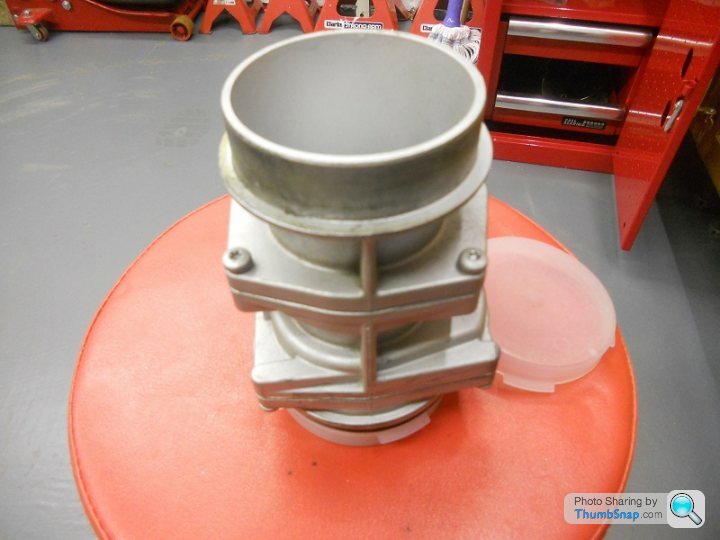
I have a standard 5am AFM removed from my 1998 450 before fitting SC500 kit & changing to larger Bosch AFM (which is now also spare as currently having MBE system installed!).
I'm happy to post to you but to be sure I'll check the part number first and post again shortly. I've no idea what it's worth and it was working perfectly before I removed it. Make me an offer by PM if of interest.
Cheers, Richard
I'm happy to post to you but to be sure I'll check the part number first and post again shortly. I've no idea what it's worth and it was working perfectly before I removed it. Make me an offer by PM if of interest.
Cheers, Richard

 |http://thumbsnap.com/8ixvLOkk[/url][url]
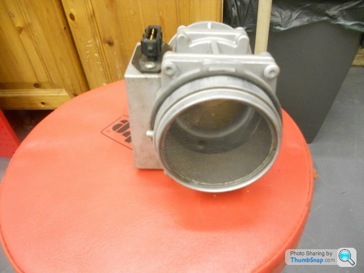 |http://thumbsnap.com/czIDlwzk[/url][url]
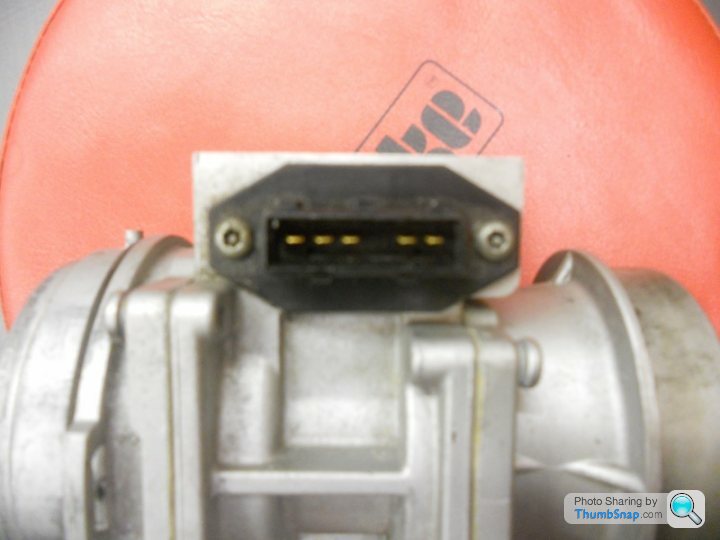 |http://thumbsnap.com/23B1jtKs[/url][url]
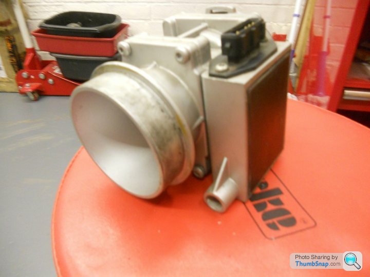 |http://thumbsnap.com/FBLRLgn5[/url][url]
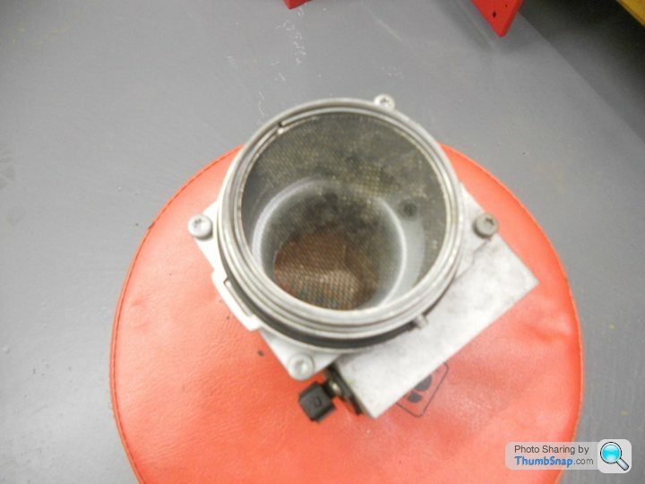 |http://thumbsnap.com/iiavHjWi[/url]
Gassing Station | Chimaera | Top of Page | What's New | My Stuff