Jobs, Progress and Questions!
Discussion


ACT said:
With the ignition switched off, test for continuity between the White ground wire and the engine block. There should be no resistance (i.e. a short circuit). Now set the multimeter to read Voltage, and insert the negative probe into the White ground wire, and the positive probe into the Red heater wire.
Now start the engine and check the voltage. There should be 12-14 Volts present when the engine is running, which is the supply for the sensor heater. This comes from the same relay that feeds the fuel pump, and shares the same fuse. If this supply is absent then the sensors will never give the correct reading.
Next the sensor signal itself should be probed. Leave the negative ground probe in the White ground wire, and put the positive probe into the Black signal wire. The voltage here should oscillate up and down between 0.2 and 1.2 Volts approximately 2 to 3 times per second. If the signal is stuck at 0 Volts or over 3.5 Volts then the sensor MAY be defective.
Monsterlime said:
Yes, I did use the positive battery terminal. Crocodile clip on to it, into the multimeter and then negative multimeter lead to the lambda (white and black, separate tests).
Only test the white for a good negative, Black is supposed to be the signal to ECU and that signal needs to be checked later once there is a good battery voltage at the heater element. Black is checked with Rover Gauge or voltmeter between it and earth/negativeMonsterlime said:
Only one meter showed 230v, the other was very low (0.21 volts). Which is annoying, since the newer meter was showing the high result.
Chances are the meter is faultyMonsterlime said:
Longer test leads arrived yesterday and this morning I managed to get back out to retest. I am confused.
Red Positive Battery to Lambda White
Engine OFF - 12 volts (both multimeters)
Engine on - 1 multimeter - 233 volts, the other - 0.21
Between battery positive and White sensor earth it should be very close to battery voltage all the time, engine on or offRed Positive Battery to Lambda White
Engine OFF - 12 volts (both multimeters)
Engine on - 1 multimeter - 233 volts, the other - 0.21
I think you've found the problem - Missing negatives/earths at sensors
Monsterlime said:
Part of the reason I am confused, is when putting the multimeter negative lead to the white lambda wire (allegedly ground) and the red multimeter wire to the black lambda wire, I would get a negative reading (-8.5v), which is surely wrong? The leads were plugged into the correct multimeter inputs as well.
There will be odd readings showing if the earths are missingConcentrate on the earths for now, they could be anywhere, they could have been rewired
Good luck
Thank you! As it happens, I was starting to think I had just confused the entire situation and decided I should throw away most of what I had done and start again. I think my results and findings are wrong, for the lambda wires, and I should trust all the docs that say white is ground, red is heater and black is signal.
Before that, and as I have been watching a LOT of Youtube videos re volt drop testing, I did that. Since red is positive/heater on the lambda side and on the loom side it is white/orange and I have repeated the tests at the relay side multiple times, I started there. Voltage drop test between white/orange and red on the lambda side showed nothing.
So, lets start again. White lambda wire to engine block and negative battery (since my wires are long enough to reach now). Both 5 Ohms. Yes, a ground issue. Sure this was fine last time, and I did confirm it on both multimeters.
I managed to get my endoscope camera into where I think the negative battery earths on the chassis (in the cabin, under the fibreglass, just before the gearbox on the centre console - multiple other PH posts indicate this!), and the battery cable looks fine. I did take some pics and will post them later, but they are on a separate computer, there are some other odd wires but might not be relevant.
To simplify further testing for you
Are you able to disconnect the ECU without too much difficulty?
With the ECU disconnected you will then be dealing with two cables at each sensor plug/socket
One cable being the positive supply from the fuel pump relay to the heater element
The other cable being the negative earth to the heater element (the culprit????)
Perhaps the above method will save some confusion?
There would no longer be any switching of the fuel pump relay with the ECU disconnected but that won't interfere with the earth testing
If you do disconnect the ECU, remove the fuel pump relay and disconnect the sensors, the only circuit left as is will be the negative earth return
I expected the 21 watt or 60 watt bulb load test to show up the fault
Edited by Penelope Stopit on Friday 20th September 19:09
Above where I comment
"Between battery positive and White sensor earth it should be very close to battery voltage all the time, engine on or off"
Used your wording there and hope it hasn't confused you, I'm guessing you understood what I meant
__________________________________________________________________________________________________
Should have read
Between battery positive and White sensor earth it should be very close to battery voltage when the fuel pump relay switches in for 2 seconds or with the engine running
__________________________________________________________________________________________________
Having given this some more thought
With there still being some doubt about the sensor wiring being terminated correctly
As mentioned above, if it's not too difficult, disconnect the ECU and sensors from their looms and remove the fuel pump relay, the sensors negative earths circuit will be all that remains (should remain, they may be faulty and not found)
Now the negative earth sensor circuit can be checked and has to be the only circuit giving any readings, it will no longer be possible to be seeing strange readings due to other circuits being connected (unless the sensor cables are shorting together in the loom)
It will also then be known what sensor loom plug apertures the negatives are terminated to
Edited by Penelope Stopit on Friday 20th September 20:28
Ok, thank you. ECU is easily accessible and can be disconnected. This will just be to test continuity/resistance along the earth, correct?
To find the join/issue, I will need to unwrap the loom and check behind the engine block as that is where the wires run, correct?
I only did from White to Battery Earth because it seemed prudent, but a standard test was White to the Engine block (from the ACT doc and other sources).
At least this is a good learning experience.
Hoping the following helps you trace the earth fault if there is one
Taken from here https://www.pistonheads.com/gassing/topic.asp?h=0&...
Reposting here with some comments removed as they were found to be incorrect
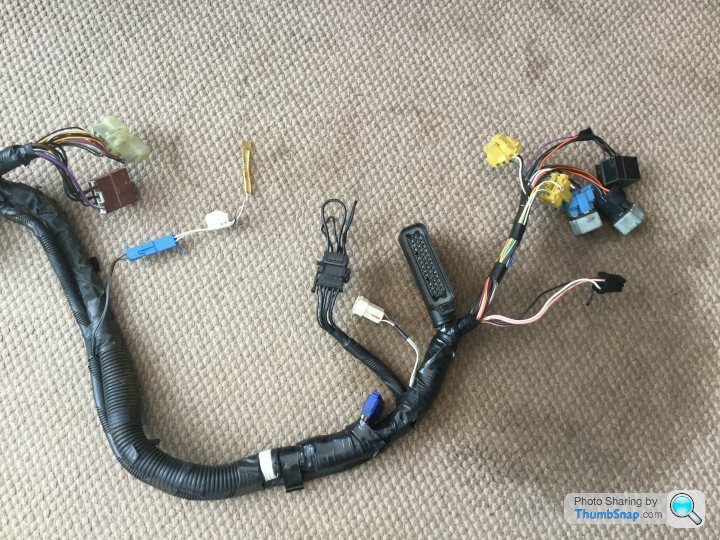
This is a Tvr wiring loom from a 2000 year 450 Chimaera. The bit that comes through the fire wall and into the Footwell.
And here's the other end of it that sits in engine bay.
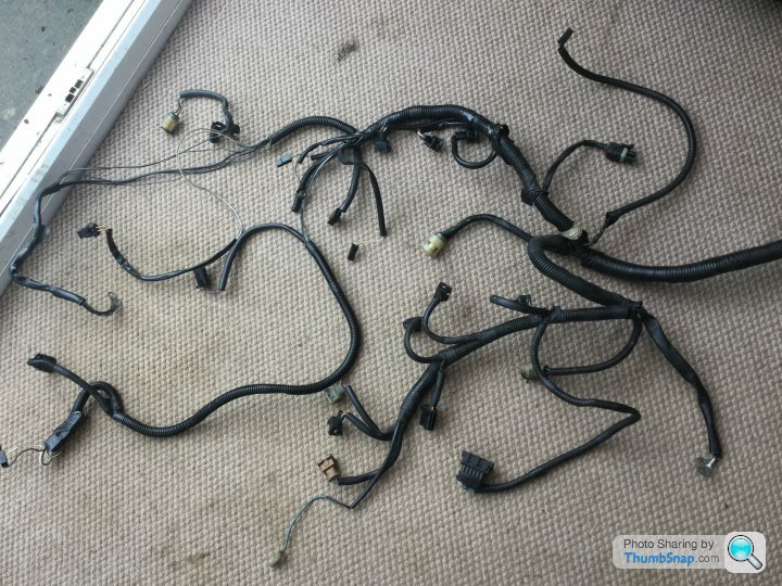
Viewed from the left hand side of the car if it was fitted.
I hope this may be of some help.
Taken from here https://www.pistonheads.com/gassing/topic.asp?h=0&...
Reposting here with some comments removed as they were found to be incorrect
Minio said:
Well confused I am!
It all started with the sentence from ACT and so far I have the following facts.
I guess there are a simple explanation but right now it looks rather complex....
It all started with the sentence from ACT and so far I have the following facts.
- No connection from any of the white probe wires to ground.
I guess there are a simple explanation but right now it looks rather complex....
blitzracing said:
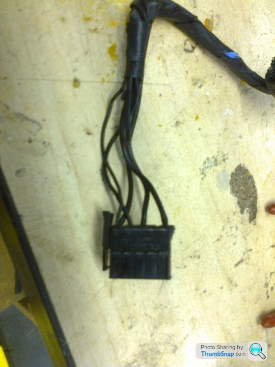
Looks like my memory has failed me on this one! Only the lambda wire is connected to the inner core of the screened wire. The earth wire runs separately alongside the screened wire and eventually ends up in this plug. This plug appears to have multiple earth points going into it, but I dont know what it plugs into. I cant find it on my Ginetta- Id suspect its in the back of the engine bay, as its a major branch of the main loom. This would seem a very likely point of failure if it had come unplugged.
ClassiChimi said:
This is a Tvr wiring loom from a 2000 year 450 Chimaera. The bit that comes through the fire wall and into the Footwell.
And here's the other end of it that sits in engine bay.
Viewed from the left hand side of the car if it was fitted.
I hope this may be of some help.
blitzracing said:
Well thats it with a loopback plug plugged into it near the main ECU plug in the footwell loom. Mine must be taped up somewhere as Ive never seen it in the footwell on mine.
Edited by blitzracing on Friday 23 September 21:23
ClassiChimi said:
Could it be as simple as this connector being dislodged !
Minio said:
Thanks a lot for the pictures and information!
It looks really promising and if the plug was missing it explains why all ground connections was missing.
It made me run all the way to the garage in the weekend, but no, my wire loom from 1993 dosen't look like that. There are no extension going to a loop back plug like that. I can identify the communication plug and the tune resistor but that's all, except for some relay sockets, that's hanging out of the loom.
The screens from the lambda probe cables are solder joined with some thick black cable inside the wire loom, just before the ECU plug.
My hope right now is that the loop back plug is in the engine bay where I can find it. Another theory is that something went wrong when the AC compressor and the compressor clutch relay was removed by the previous owner.
Minio said:
The mystery is solved, at last!
I had another nice session in the garage yesterday where I started to search for the connector, mentioned above, somewhere on my wire loom.
It was not inside the car so I start looking in the engine bay. There was 3 black suspicious wires coming out of the loom right before it passed through the fire wall.
After removing the inlet manifold I was able to spot the failure, they where hit by some blunt object right before the join. Or maybe attacked by a rat.
Anyway it all explains why nothing was connected to ground.
Thanks for all help and encouragement.


Ok, thank you both. I had read that thread, several times, but was really hoping it wouldn't go that far. 
I haven't had the time to do anything else yet, but am guessing if I do need to get access to the point, removing the inlet manifold etc will be required? How hard/effort is involved in that? How many hours should I book in with the wife? lol
Thanks
I haven't had the time to do anything else yet, but am guessing if I do need to get access to the point, removing the inlet manifold etc will be required? How hard/effort is involved in that? How many hours should I book in with the wife? lol
Thanks
Monsterlime said:
Ok, thank you both. I had read that thread, several times, but was really hoping it wouldn't go that far.
I haven't had the time to do anything else yet, but am guessing if I do need to get access to the point, removing the inlet manifold etc will be required? How hard/effort is involved in that? How many hours should I book in with the wife? lol
Thanks
You could PM Steve_D and ask him if anything else earths at that same boltI haven't had the time to do anything else yet, but am guessing if I do need to get access to the point, removing the inlet manifold etc will be required? How hard/effort is involved in that? How many hours should I book in with the wife? lol
Thanks
You could cheat if only the sensors earth to the rear of the head
New cables could be routed from the sensor plugs (solder into the cables if need be and cover the joint with adhesive heat-shrink sleeving. http://adhesiveheatshrink.com/ lots of companies sell it) to a more accessible earth point of your choice
Thanks, but after thinking about it I may try and make the most of the pain and put on a ported inlet manifold, trumpet base and 72mm plenum.
Other than making a Megasquirt (can you imagine me doing that) install potentially easier, anything else I should do with it off?
Won’t be able to do it soon, on holiday next week and the weather is not on my side either right now. I also want to take it all off before ordering bits (fun bits that is, new gaskets etc will be ordered first) just in case there are some unexpected surprises under there.
Holiday is in Portugal!
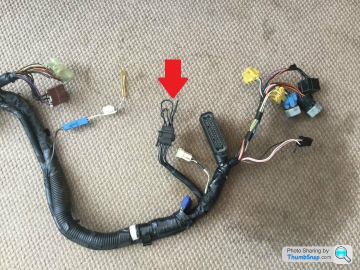
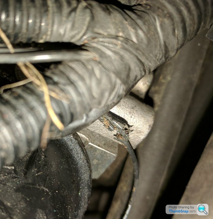
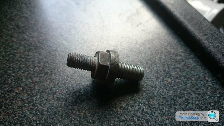
Some good progress was made today, I at least am now pretty sure what the problem is. After reading this, and watching a few videos I could see exactly where the stud for the earth on the rear of the engine was supposed to be, and I had some time today, so had a look/feel.
Aren't these supposed to be connected to something?
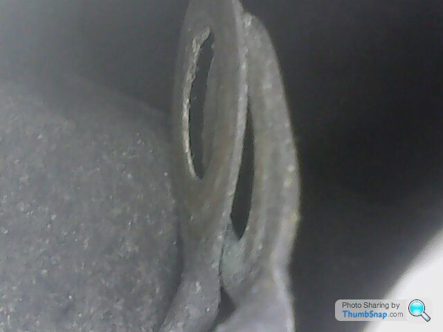
Sure this shouldn't be empty..

Does anyone know what the thread size (and length) for the stud and bolt should be? No idea why it isn't there, it either came out or someone removed it and never put it back.
I did also take the Plenum off to check it out, and unfortunately there were no nice surprises under there. All standard, but there was oil in in the top and when I unplugged the stepper motor connection, I realised the stepper itself just spins in the housing and has been MacGuyver cable tied up so it doesn't come out. That surely isn't right, is it? Thats another job on the list of things to fix!
Should I be worried about this -
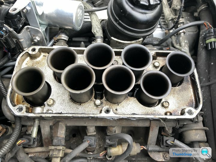
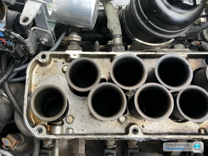
Taken before I cleaned it all up and resealed the Plenum to the trumpet base!
Some good progress was made today, I at least am now pretty sure what the problem is. After reading this, and watching a few videos I could see exactly where the stud for the earth on the rear of the engine was supposed to be, and I had some time today, so had a look/feel.
Aren't these supposed to be connected to something?
Sure this shouldn't be empty..
Does anyone know what the thread size (and length) for the stud and bolt should be? No idea why it isn't there, it either came out or someone removed it and never put it back.
I did also take the Plenum off to check it out, and unfortunately there were no nice surprises under there. All standard, but there was oil in in the top and when I unplugged the stepper motor connection, I realised the stepper itself just spins in the housing and has been MacGuyver cable tied up so it doesn't come out. That surely isn't right, is it? Thats another job on the list of things to fix!
Should I be worried about this -
Taken before I cleaned it all up and resealed the Plenum to the trumpet base!
Monsterlime said:
Holiday is in Portugal!
Some good progress was made today, I at least am now pretty sure what the problem is. After reading this, and watching a few videos I could see exactly where the stud for the earth on the rear of the engine was supposed to be, and I had some time today, so had a look/feel.
Aren't these supposed to be connected to something?
Great news, all worthwhile thenSome good progress was made today, I at least am now pretty sure what the problem is. After reading this, and watching a few videos I could see exactly where the stud for the earth on the rear of the engine was supposed to be, and I had some time today, so had a look/feel.
Aren't these supposed to be connected to something?
Good to know you've very likely found the earth fault
Hopefully someone will be along shortly with the thread size
Enjoy Portugal, it's been another hot day in Greece

Gassing Station | Chimaera | Top of Page | What's New | My Stuff