Jobs, Progress and Questions!
Discussion


I actually have some good quality thermal CPU paste sitting around, so may do the swap. I didn't put gobs on, just enough and I did clean up the plate it mounts to before refitting. I did consider using the CPU paste, but assumed the stuff supplied would be sufficient.
I got the new resistors yesterday, they are unbranded so not Lucas (I guess I was expecting too much), but both read correctly so have put them in. However, after watching this video of Phazed's car - https://www.youtube.com/watch?v=fa5oKqEgkME (I browse PH a lot), his car does exactly the same thing on gear change, so I wonder if this is a case of "they all do it", although I am certain my old one didn't.
In Lambda news, I think they are both dead - https://www.youtube.com/watch?v=O0FZaWmf6c0 I found the connections both sides of the Plenum, simple when you know they are there! I used the probes in various places, on the different connections and got the same results, I just videoed those two. Shame I can't find them at a reasonable cost from that US eBay seller. Is it worth just buying one, testing it to make sure this is right? I assume if there was a break in the wiring somewhere I would be getting nothing. I did try 2 multimeters as well!
They were working, I saw them doing so on Rovergauge, so I do wonder if my misadventure with the ignition amp killed them, and somehow blew the fuse I replaced.
Re the blue relay, there is a white/orange and a white cable going into it on one 87 pin.
Monsterlime said:
I actually have some good quality thermal CPU paste sitting around, so may do the swap. I didn't put gobs on, just enough and I did clean up the plate it mounts to before refitting. I did consider using the CPU paste, but assumed the stuff supplied would be sufficient.
I got the new resistors yesterday, they are unbranded so not Lucas (I guess I was expecting too much), but both read correctly so have put them in. However, after watching this video of Phazed's car - https://www.youtube.com/watch?v=fa5oKqEgkME (I browse PH a lot), his car does exactly the same thing on gear change, so I wonder if this is a case of "they all do it", although I am certain my old one didn't.
In Lambda news, I think they are both dead - https://www.youtube.com/watch?v=O0FZaWmf6c0 I found the connections both sides of the Plenum, simple when you know they are there! I used the probes in various places, on the different connections and got the same results, I just videoed those two. Shame I can't find them at a reasonable cost from that US eBay seller. Is it worth just buying one, testing it to make sure this is right? I assume if there was a break in the wiring somewhere I would be getting nothing. I did try 2 multimeters as well!
They were working, I saw them doing so on Rovergauge, so I do wonder if my misadventure with the ignition amp killed them, and somehow blew the fuse I replaced.
Re the blue relay, there is a white/orange and a white cable going into it on one 87 pin.
If the supply and return/earth were good enough to power a 21 Watt or 60 Watt bulb they will power the Lambda Heater ElementsI got the new resistors yesterday, they are unbranded so not Lucas (I guess I was expecting too much), but both read correctly so have put them in. However, after watching this video of Phazed's car - https://www.youtube.com/watch?v=fa5oKqEgkME (I browse PH a lot), his car does exactly the same thing on gear change, so I wonder if this is a case of "they all do it", although I am certain my old one didn't.
In Lambda news, I think they are both dead - https://www.youtube.com/watch?v=O0FZaWmf6c0 I found the connections both sides of the Plenum, simple when you know they are there! I used the probes in various places, on the different connections and got the same results, I just videoed those two. Shame I can't find them at a reasonable cost from that US eBay seller. Is it worth just buying one, testing it to make sure this is right? I assume if there was a break in the wiring somewhere I would be getting nothing. I did try 2 multimeters as well!
They were working, I saw them doing so on Rovergauge, so I do wonder if my misadventure with the ignition amp killed them, and somehow blew the fuse I replaced.
Re the blue relay, there is a white/orange and a white cable going into it on one 87 pin.
During engine run time the sensors are continuously powered, doubtful your work caused them to fail
Have you measured the resistance of the heater elements, are they showing as open circuit?
Well, I mean more when I drove the car and the ground for the ignition amp may have been suspect, which is what I would expect killed the previous amp. I could be wrong though!
Re the heater element, I assume for this I would disconnect the probe from the loom, and then test the resistance that way? Since there is only one heater wire, I assume I will still need to do this with the white wire and the black wire?
Re the heater element, I assume for this I would disconnect the probe from the loom, and then test the resistance that way? Since there is only one heater wire, I assume I will still need to do this with the white wire and the black wire?
Monsterlime said:
Re the heater element, I assume for this I would disconnect the probe from the loom, and then test the resistance that way? Since there is only one heater wire, I assume I will still need to do this with the white wire and the black wire?
Yes that's it, disconnect and check themCheck the resistance of the elements as shown in the below diagram, the top pair of cables
Got it, thanks.
I did do some other tests, based on the ACT tests and I am now a bit confused.
I tested the resistance from the white wire to the engine block, on both, and that seemed fine. I also tested the voltage on the white and red wires, and this is where I am confused.
On the passenger side lambda, negative to white and positive to red, I got what I would have expected when testing white and black (according to ACT) - https://www.youtube.com/watch?v=PcaD6v_HgcQ
When I did the same to the drivers side lambda, nothing, no movement at all.
The passenger side seems fine, according to all of the tests, but it is still throwing an error code in the ECU. But, my wiring seems wrong, the signal is on the red wire and not the black one?
Monsterlime said:
Got it, thanks.
I did do some other tests, based on the ACT tests and I am now a bit confused.
I tested the resistance from the white wire to the engine block, on both, and that seemed fine. I also tested the voltage on the white and red wires, and this is where I am confused.
On the passenger side lambda, negative to white and positive to red, I got what I would have expected when testing white and black (according to ACT) - https://www.youtube.com/watch?v=PcaD6v_HgcQ
When I did the same to the drivers side lambda, nothing, no movement at all.
The passenger side seems fine, according to all of the tests, but it is still throwing an error code in the ECU. But, my wiring seems wrong, the signal is on the red wire and not the black one?
Did the heater elements check out ok?I did do some other tests, based on the ACT tests and I am now a bit confused.
I tested the resistance from the white wire to the engine block, on both, and that seemed fine. I also tested the voltage on the white and red wires, and this is where I am confused.
On the passenger side lambda, negative to white and positive to red, I got what I would have expected when testing white and black (according to ACT) - https://www.youtube.com/watch?v=PcaD6v_HgcQ
When I did the same to the drivers side lambda, nothing, no movement at all.
The passenger side seems fine, according to all of the tests, but it is still throwing an error code in the ECU. But, my wiring seems wrong, the signal is on the red wire and not the black one?
Take a close look at the terminal configuration of the passenger side sensor plug and engine loom socket that connects to it, compare the configuration with the drivers side sensor and engine loom plug/socket, there is a possibility that plugs/sockets have been tampered with
I'm off-line shortly (today or tomorrow) for several days, plenty of others will help if you don't find the problem after checking the above
I haven't had a chance to check the heater elements. It was on my list for today (I had a car maintenance pass from the wife). Unfortunately, I didn't get time to get to them, due to a small calamity (perhaps I am the calamity), that I am hopeful I can fix without too much stress (I expect my hopes to be dashed here).
I had decided to start with plugs, leads, dizzy and rotor. Those Beru extender things are awful, and are now in the bin. The plugs were a LOT harder to get out than I expected, and I was being very careful. They all came out ok eventually, except the 2nd plug on the passenger/left hand side (number 3?). It took a fair bit of time and effort, but it came out. Unfortunately, I think the person who did this last threaded it partially and then managed to get it in, and now I cannot get it back in, and don't want to force it.
It looks to me that the thread further in is ok, so I have ordered this - https://www.amazon.co.uk/gp/product/B0086306NO I fully expect to be told this won't work and I am going to have to strip the engine to get it drilled out. I have also ordered a more "normal" thread chaser, as a cover all the bases, but I would rather the first one was successful.
I assume I should keep the above oiled/lubricated while using it?
I did carry on and replace the rest of the plugs, the dizzy cap, rotor and leads (the diagram in the bible did not match the orientation of my dizzy cap, but I just put it back how it was) and socks on the leads. Once this plug is sorted, the ignition refresh will be done.
This is a bit disheartening, but will hopefully get it sorted soon.
Or maybe I should buy that 5.3ltr V8 Developments engine on eBay..

You may have already viewed https://www.youtube.com/watch?v=K1BhfhsinJs
Have you a small USB camera that will plug into a laptop and allow you to view the damaged threads?
The tool should work
Yes apply plenty of grease to the tool so that the metal particles stick to the tool as it cuts rather than them going into the bore, the grease will help with the cutting
Good luck, what a pain of a problem
Thats a great video! I had already seen this one - https://www.youtube.com/watch?v=3UK8kEAnHVk, but the other one is a lot more detailed, gives me confidence I can do it. I hope!
I haven't got a camera, and it is one of those things sitting in my Amazon wishlist, so I should get one.
My only concern with the tool is that it might be too long for the clearance between the block and the body. I left everything I had removed loose, like the induction elbow so it is all easy to get out. The dipstick holder/tube might be an issue but hopefully it will move enough when I undo the screw that has it held in place.
Success, I hope!
Tool arrived today, slightly surprisingly, so I found some spare time at work and went out to hopefully fix it. This thing is a bit fiddly, and none of the YouTube videos show that often, for some reason, it will not tighten up and pull the little "puck" in the bottom up and expand the thread. Easy to do when it is outside of the car, less easy when it is in but after some perseverance, I seem to have managed it.
I didn't go all in straight away and just used it a couple of times, and it seems to have cleaned up the thread enough for me to get the plug back in and tightened up.
She sounds ok to me - https://www.youtube.com/watch?v=Pl-SNUiTGAg I know I need to take her out for a run to make sure nothing pops, but I'll take the success for now!
A sample of the plugs look like this -
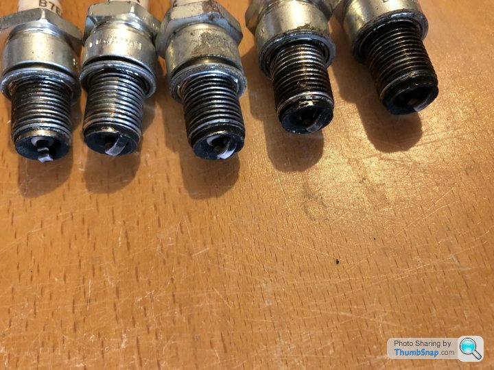
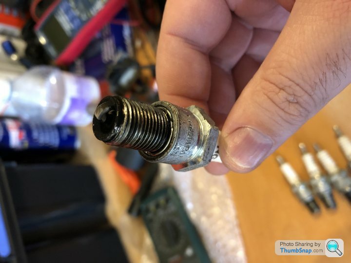
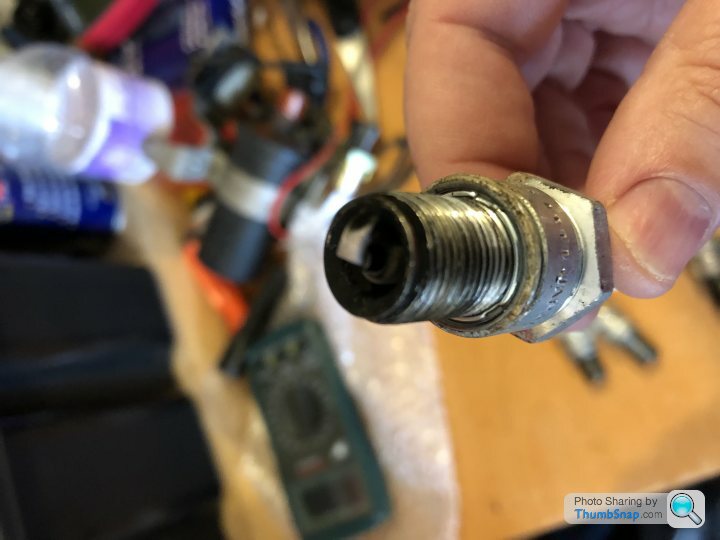
What do we think of their condition? To my (very) untrained eye, I don't think they look great and show signs of over fueling?
The Lambda will wait for another day, I didn't have a chance to mess with it (and the drivers side one is in a VERY awkward position, I'll probably relocate it when tested), and my back was killing me.
I should be clearer about them though - I got the same "wrong" readings from both Lambda's. I was getting the "signal" on the red wire and the voltage on the black wire, whereas ACT has that the other way around (white was still ground). I haven't been able to check the wiring along the run very closely, but the passenger side looked unmodified.
Tool arrived today, slightly surprisingly, so I found some spare time at work and went out to hopefully fix it. This thing is a bit fiddly, and none of the YouTube videos show that often, for some reason, it will not tighten up and pull the little "puck" in the bottom up and expand the thread. Easy to do when it is outside of the car, less easy when it is in but after some perseverance, I seem to have managed it.
I didn't go all in straight away and just used it a couple of times, and it seems to have cleaned up the thread enough for me to get the plug back in and tightened up.
She sounds ok to me - https://www.youtube.com/watch?v=Pl-SNUiTGAg I know I need to take her out for a run to make sure nothing pops, but I'll take the success for now!
A sample of the plugs look like this -
What do we think of their condition? To my (very) untrained eye, I don't think they look great and show signs of over fueling?
The Lambda will wait for another day, I didn't have a chance to mess with it (and the drivers side one is in a VERY awkward position, I'll probably relocate it when tested), and my back was killing me.
I should be clearer about them though - I got the same "wrong" readings from both Lambda's. I was getting the "signal" on the red wire and the voltage on the black wire, whereas ACT has that the other way around (white was still ground). I haven't been able to check the wiring along the run very closely, but the passenger side looked unmodified.
Monsterlime said:
Success, I hope!
Tool arrived today, slightly surprisingly, so I found some spare time at work and went out to hopefully fix it. This thing is a bit fiddly, and none of the YouTube videos show that often, for some reason, it will not tighten up and pull the little "puck" in the bottom up and expand the thread. Easy to do when it is outside of the car, less easy when it is in but after some perseverance, I seem to have managed it.
I didn't go all in straight away and just used it a couple of times, and it seems to have cleaned up the thread enough for me to get the plug back in and tightened up.
Great news about the tool workingTool arrived today, slightly surprisingly, so I found some spare time at work and went out to hopefully fix it. This thing is a bit fiddly, and none of the YouTube videos show that often, for some reason, it will not tighten up and pull the little "puck" in the bottom up and expand the thread. Easy to do when it is outside of the car, less easy when it is in but after some perseverance, I seem to have managed it.
I didn't go all in straight away and just used it a couple of times, and it seems to have cleaned up the thread enough for me to get the plug back in and tightened up.
Thank you, it is a bit of a relief!
Back to Lambda fun! I have now tested the heater circuit on both (and consider my wiring seems to be the opposite of what ACT says it should be), on both sides White and Black read as 6.5 ohms, and White and Red read as 0.L which am pretty sure means Open and therefore no continuity.
I am considering picking up a lambda sensor to try and confirm the wiring, and see if it makes a difference. This I suspect is too cheap and means it is a Zirconia part - https://rimmerbros.com/Item--i-ERR6729P and not a Titania part, which is disappointing.
Before I do, anything else to try? Should I look to test at the ECU side?
Due to the drivers side being so awkward I ended up testing it at the Plenum connection, I just couldn't really get to the connector without lifting the car, so am confident up to there is ok.
Penelope Stopit said:
Yes that's it, disconnect and check them
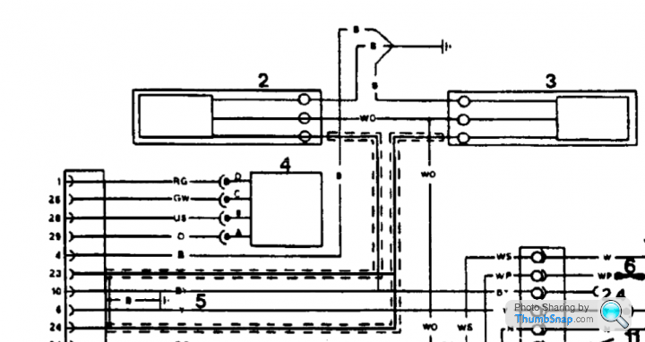
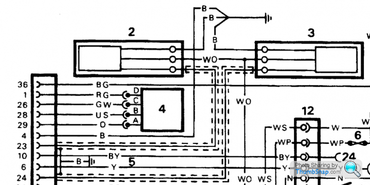
Check the resistance of the elements as shown in the below diagram, the top pair of cables
Surely that diagram's wrong. It appears to show the sensor signal wire from lambda (3) going to both pins 23 and 24 of the ecu, and the signal from lambda (2) spliced into pin 10 which is the MIL light .. ?Check the resistance of the elements as shown in the below diagram, the top pair of cables
What am I reading wrong here ?
spitfire4v8 said:
Penelope Stopit said:
Yes that's it, disconnect and check them
Check the resistance of the elements as shown in the below diagram, the top pair of cables
Surely that diagram's wrong. It appears to show the sensor signal wire from lambda (3) going to both pins 23 and 24 of the ecu, and the signal from lambda (2) spliced into pin 10 which is the MIL light .. ?Check the resistance of the elements as shown in the below diagram, the top pair of cables
What am I reading wrong here ?
The above was found here https://www.pistonheads.com/gassing/topic.asp?h=0&...
blitzracing said:
The heater wires only have 12v when the engine is running, or during the 2 seconds during ignition turn on, its the same supply as the fuel pump, so if thats running the lambda heaters should have power. Its the red wire to ground. The trim shows "adding fuel" so the ECU has 0 volts from the lambda sensors, and no heater will do that, as the heater supply is linked to the lambda output. Check fuses in the 14CUX loom near the relays.
Manuals here:
https://www.dropbox.com/sh/i0acxr8nwr10ow6/AACcZ2H...
White is ground, red is heater, black is probe output. RoverGauge should be throwing fault codes for no lambda outputs.
The below diagram seems to be error freeManuals here:
https://www.dropbox.com/sh/i0acxr8nwr10ow6/AACcZ2H...
White is ground, red is heater, black is probe output. RoverGauge should be throwing fault codes for no lambda outputs.
Monsterlime said:
Thank you, it is a bit of a relief!
Back to Lambda fun! I have now tested the heater circuit on both (and consider my wiring seems to be the opposite of what ACT says it should be), on both sides White and Black read as 6.5 ohms, and White and Red read as 0.L which am pretty sure means Open and therefore no continuity.
I am considering picking up a lambda sensor to try and confirm the wiring, and see if it makes a difference. This I suspect is too cheap and means it is a Zirconia part - https://rimmerbros.com/Item--i-ERR6729P and not a Titania part, which is disappointing.
Before I do, anything else to try? Should I look to test at the ECU side?
Due to the drivers side being so awkward I ended up testing it at the Plenum connection, I just couldn't really get to the connector without lifting the car, so am confident up to there is ok.
I seem to recall you mentioning how difficult it is to check the wiring at the lambda sensors to engine loom plugs/sockets (I could be wrong), If you could check each end of the plugs and sockets the sensors wiring will very likely show as Red being used for the signal cables rather than Black as in the diagrams and ACT TestBack to Lambda fun! I have now tested the heater circuit on both (and consider my wiring seems to be the opposite of what ACT says it should be), on both sides White and Black read as 6.5 ohms, and White and Red read as 0.L which am pretty sure means Open and therefore no continuity.
I am considering picking up a lambda sensor to try and confirm the wiring, and see if it makes a difference. This I suspect is too cheap and means it is a Zirconia part - https://rimmerbros.com/Item--i-ERR6729P and not a Titania part, which is disappointing.
Before I do, anything else to try? Should I look to test at the ECU side?
Due to the drivers side being so awkward I ended up testing it at the Plenum connection, I just couldn't really get to the connector without lifting the car, so am confident up to there is ok.
The ACT test mentions 4 to 6 Ohms is to be expected when testing the heater circuits of the sensors (White and Red) with them disconnected from the engine loom
The YT video White&Red Voltage Test https://www.youtube.com/watch?v=PcaD6v_HgcQ
tells us that although White and Red should be wired to the sensors heater elements they aren't, the White and Red cables of your cars sensors are used for the signals to the ECU (perhaps cheap Chinese incorrectly colour coded sensors????)
Yes, with everything connected you can check for the very same signals at ECU Pins 23 and 24 (be careful, multimeter set to DC Volts and multimeter leads in the correct termination points for DC Volts, I know you know but.......)
Have you read the beginning of the ACT Lambda Sensors explanation of operation, it mentions engine temperature, RPM and throttle position?
Gassing Station | Chimaera | Top of Page | What's New | My Stuff