LT77 speedo sensor
Discussion


blitzracing said:
Thankyou! -A tuned circuit then... Ill have a look at the waveforms on the coil ends and see what is going on. I appreciate the PNP bit, but can I just check the ground path? The brown wire is marked as 12v on the lucas wiring, so you cant pull that to ground ?
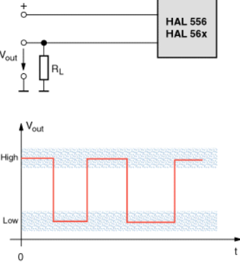
Blitz, forget the Lucas wiring convention for a moment and look at the application wiring diagram for the transducer shown in Griff400's posting above.In this case Brown doubles up as switched earth and O/P signal line (V OUT) if you like.
For example:
oh boy- got to love this - so brown is not 12v and yellow and black is not the speed signal as in the Lucas designation but the opposite way around ... I would not mind if it was TVR wiring, but is this not a bog standard lucas part? Oh well, Ill get a scope on it tomorrow with the correct polarity and have a play. All the semiconductors are in one piece on the one Ive pulled to bits.
blitzracing said:
oh boy- got to love this - so brown is not 12v and yellow and black is not the speed signal as in the Lucas designation but the opposite way around ... I would not mind if it was TVR wiring, but is this not a bog standard lucas part? Oh well, Ill get a scope on it tomorrow with the correct polarity and have a play. All the semiconductors are in one piece on the one Ive pulled to bits.
Apparently, the actual LT77/SDI road speed transducer was manufactured by Caerbont Automotive Instruments and is not a Lucas part. It does however include a Lucas three pin RISTS circular connector (and of course only two pins are used), which may be the cause of your confusion ;-)Steve_D said:
Can anyone advise how you test one of these?
Have a TES2805/2001 that may be suspect.
Steve
In got a working one today, they are easy to test- you just need the 12 volts on one wire, and the output wire goes to ground via a 1k resistor. Then measure the voltage across the resistor as you spin the gear. A DVM will show you a shifting voltage between about 8 and 2 volts as it rotates, or a scope will show a clear pulse signal. It does need to be rotated fast enough to see the signal, but you can do this by hand. The input impedance of a TVR speedo is only 400 ohms, and without a similar low resistance to ground the sensor wont work.Have a TES2805/2001 that may be suspect.
Steve
blitzracing said:
Steve_D said:
Can anyone advise how you test one of these?
Have a TES2805/2001 that may be suspect.
Steve
In got a working one today, they are easy to test- you just need the 12 volts on one wire, and the output wire goes to ground via a 1k resistor. Then measure the voltage across the resistor as you spin the gear. A DVM will show you a shifting voltage between about 8 and 2 volts as it rotates, or a scope will show a clear pulse signal. It does need to be rotated fast enough to see the signal, but you can do this by hand. The input impedance of a TVR speedo is only 400 ohms, and without a similar low resistance to ground the sensor wont work.Have a TES2805/2001 that may be suspect.
Steve
Were you reading on AC or DC?
Could you read Hz in some way other than a scope? (I have HZ on my DVM)
Steve
Steve_D said:
I have no way to dispute Caerbont making them but the circuit board inside is clearly marked Lucas.
Steve
Although under temporary Lucas ownership in the 80s, it is clearly evident Caerbont specified the unit connector wiring using a convention that was not compliant with the Lucas colour coding scheme. Steve
Gassing Station | Griffith | Top of Page | What's New | My Stuff