Instructions to change fuel maps on 14CUX Griffith, Chimaera
Discussion


CGCobra said:
....
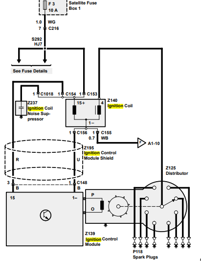
3) Does anyone have a circuit diagram to pin 39 of the 14CUX?
Here you go:3) Does anyone have a circuit diagram to pin 39 of the 14CUX?

Results of oscilloscope check on the injector firing circuits:
- Pin input line 39 (white/black) ignition spark signal from coil.
- Pin output line 11 (yellow/white) injector bank firing pulse for even bank.
- Pin output line 13 (yellow/blue) injector bank firing pulse for odd bank.
- Connect 'scope Channel 1 to line 39, Channel 2 to line 11 and Channel 3 to line 13, all with good probe earths.

Where:
- Top white trace is the input ignition spark pulse waveform.
- Green trace is the even bank injector firing pulse waveform.
- Purple trace is the odd bank.
A time base setting of 5 mS/div was set giving approx 16 mS spark pulse period, and approx 3 mS injector pulse width. Voltage settings as shown.
Edited by davep on Friday 25th June 15:38
stevesprint said:
Issac
How’s your supercharged Triumph TR7 Bullet?
Here’s a link to my latest TunerPro definition file dated 22/03/2020
http://www.remap-14cux.uk/TunerPro/TunerPro14CUXCo...
Please let me know if you need anything adding or fixing and I’ll do my best.
If you mean the one table ‘accelPumpTable’ in the data.asm then sorry no, however
I have got my head around the six row ‘throttle pot direction & rate’ tables in each map which are called in TunerPro “Map (1-5) THROTTLE TABLE”.
1st Row Temperature (hot to cold, left to right) only one column comes into play at a time
2nd Row Throttle Opening Max throttle fuel added
3rd Row Throttle Closing Max throttle fuel subtracted
4th Row Throttle Open Multiplier
5th Row Throttle Closing Multiplier
6th Row Throttle Opening extra fuel decay time
Setting the decay time down to 01 the extra throttle fuel does NOT decay below 4000rpm at which point this table is ignored due to the processor running out of time between sparks, therefore reducing row 6 increases the decay time.
This a very important function of the throttle pot which you can see with afr guage when the max is set to 01 the AFR goes very lean for a split second and the engine hesitates when suddenly flooring the throttle. The Bosch AFM I use has a quicker response time so I had to reduce this throttle pot extra fuel, I believe this throttle fuel could be increased to eliminate hesitation with cheap copy 5AM AFMs.
Hi Steve, we are both still running, sort of, neither of us are spring chickens.How’s your supercharged Triumph TR7 Bullet?
Here’s a link to my latest TunerPro definition file dated 22/03/2020
http://www.remap-14cux.uk/TunerPro/TunerPro14CUXCo...
Please let me know if you need anything adding or fixing and I’ll do my best.
If you mean the one table ‘accelPumpTable’ in the data.asm then sorry no, however
I have got my head around the six row ‘throttle pot direction & rate’ tables in each map which are called in TunerPro “Map (1-5) THROTTLE TABLE”.
1st Row Temperature (hot to cold, left to right) only one column comes into play at a time
2nd Row Throttle Opening Max throttle fuel added
3rd Row Throttle Closing Max throttle fuel subtracted
4th Row Throttle Open Multiplier
5th Row Throttle Closing Multiplier
6th Row Throttle Opening extra fuel decay time
Setting the decay time down to 01 the extra throttle fuel does NOT decay below 4000rpm at which point this table is ignored due to the processor running out of time between sparks, therefore reducing row 6 increases the decay time.
This a very important function of the throttle pot which you can see with afr guage when the max is set to 01 the AFR goes very lean for a split second and the engine hesitates when suddenly flooring the throttle. The Bosch AFM I use has a quicker response time so I had to reduce this throttle pot extra fuel, I believe this throttle fuel could be increased to eliminate hesitation with cheap copy 5AM AFMs.
The issue I am having seems to be hesitation as a swapped TPS from a friends car did not cure the issue nor did the AFM from the same source,I still accelerate then nearly headbutt the windscreen before I get slammed back into the headrest and it accelerates like a scalded cat. Your point on the response time of the 3/5AM AFM would explain why this might happen. The length of the induction piping between supercharger and inlet manifold probably does not help either and I did consider moving the AFM downstream of the supercharger, but one thing at a time seems to be the pragmatic thing to do.
I have a 20AM with trimmer ready to go in and have been given a matched set of Siemens injectors rated at 220 cc/min so they should be a good match for each other, don't know how fast a 20 AM responds compared to a 3AM though. .
If the throttle pedal is not stamped on but smoothly pushed the issue does not arise so it is still driveable.
Many thanks for the help, it is very much appreciated.
davep said:
Here you go:
Results of oscilloscope check on the injector firing circuits:
- Pin input line 39 (white/black) ignition spark signal from coil.
- Pin output line 11 (yellow/white) injector bank firing pulse for even bank.
- Pin output line 13 (yellow/blue) injector bank firing pulse for odd bank.
- Connect 'scope Channel 1 to line 39, Channel 2 to line 11 and Channel 3 to line 13, all with good probe earths.
Where:
- Top white trace is the input ignition spark pulse waveform.
- Green trace is the even bank injector firing pulse waveform.
- Purple trace is the odd bank.
A time base setting of 5 mS/div was set giving approx 16 mS spark pulse period, and approx 3 mS injector pulse width. Voltage settings as shown.
Hi DaveResults of oscilloscope check on the injector firing circuits:
- Pin input line 39 (white/black) ignition spark signal from coil.
- Pin output line 11 (yellow/white) injector bank firing pulse for even bank.
- Pin output line 13 (yellow/blue) injector bank firing pulse for odd bank.
- Connect 'scope Channel 1 to line 39, Channel 2 to line 11 and Channel 3 to line 13, all with good probe earths.
Where:
- Top white trace is the input ignition spark pulse waveform.
- Green trace is the even bank injector firing pulse waveform.
- Purple trace is the odd bank.
A time base setting of 5 mS/div was set giving approx 16 mS spark pulse period, and approx 3 mS injector pulse width. Voltage settings as shown.
Edited by davep on Friday 25th June 15:38
Thanks for that.
The main thing I'm interested in the ingnition circuit is what happesn inside the 14CUX, this is shown on your second diagram and just looks like a transistor which is what I was expecting but if that is the case it seems strange (to me) that when I put my meter on the black/white wire to pin 9 I get 12.2V, I'd expect that to be open circuit or ground (possibly via a resistance but getting voltage there was not what I expected.
Looking at the white trace. I'm assuming the X axis divisions are mS? (period of circa 15.5 mS consistent with around 1000RPM)?
I'm assuming the 3 division 'ramp' is the charging period for the coil and what follows is the firing interval (at around 8 vertical divisions) for about 1.5mS, followed by the flyback pulse going up to 20 divisions (was expecting higher than that) then battery voltage for the remainder while waiting for coil to charge for next cycle?
I need to think about this for a while as I'm not sure what it's telling me about what's happening from the 14CUX side of things, particularly why I'm getting a voltage feed on pin 39 (or at least the wire from it). I'm confused and my brain needs a rest.
What I'm trying to do here is provide an RPM signal to the 14CUX without the need for the coil, that is a nice simple square wave or something similar.
CGCobra said:
Hi Dave
Thanks for that.
The main thing I'm interested in the ingnition circuit is what happesn inside the 14CUX, this is shown on your second diagram and just looks like a transistor which is what I was expecting but if that is the case it seems strange (to me) that when I put my meter on the black/white wire to pin 9 I get 12.2V, I'd expect that to be open circuit or ground (possibly via a resistance but getting voltage there was not what I expected.
Looking at the white trace. I'm assuming the X axis divisions are mS? (period of circa 15.5 mS consistent with around 1000RPM)?
I'm assuming the 3 division 'ramp' is the charging period for the coil and what follows is the firing interval (at around 8 vertical divisions) for about 1.5mS, followed by the flyback pulse going up to 20 divisions (was expecting higher than that) then battery voltage for the remainder while waiting for coil to charge for next cycle?
I need to think about this for a while as I'm not sure what it's telling me about what's happening from the 14CUX side of things, particularly why I'm getting a voltage feed on pin 39 (or at least the wire from it). I'm confused and my brain needs a rest.
What I'm trying to do here is provide an RPM signal to the 14CUX without the need for the coil, that is a nice simple square wave or something similar.
CG, the ECM transistor is simply an annotation symbol to indicate "this is an electronic unit".Thanks for that.
The main thing I'm interested in the ingnition circuit is what happesn inside the 14CUX, this is shown on your second diagram and just looks like a transistor which is what I was expecting but if that is the case it seems strange (to me) that when I put my meter on the black/white wire to pin 9 I get 12.2V, I'd expect that to be open circuit or ground (possibly via a resistance but getting voltage there was not what I expected.
Looking at the white trace. I'm assuming the X axis divisions are mS? (period of circa 15.5 mS consistent with around 1000RPM)?
I'm assuming the 3 division 'ramp' is the charging period for the coil and what follows is the firing interval (at around 8 vertical divisions) for about 1.5mS, followed by the flyback pulse going up to 20 divisions (was expecting higher than that) then battery voltage for the remainder while waiting for coil to charge for next cycle?
I need to think about this for a while as I'm not sure what it's telling me about what's happening from the 14CUX side of things, particularly why I'm getting a voltage feed on pin 39 (or at least the wire from it). I'm confused and my brain needs a rest.
What I'm trying to do here is provide an RPM signal to the 14CUX without the need for the coil, that is a nice simple square wave or something similar.
It's some time since I looked at this, annoyingly there is no schematic for the 14CUX PCB available, as far as I know. In the past I've used the information in the Motorola MC6801U4 data sheet and what the code is doing to determine what happens between pin 39 of the module connector, pin 8 of the ECU chip, and P20 of Port 2:
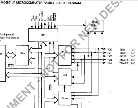
Looking at my notes, all I've got is Port 2's TIN1 (P20) showing as a TTL load Darlington transistor input switch. Essentially the Port 2/ Timer circuit detects the leading edge of the ignition pulses, an event which both triggers a fuelling interrupt request to the MPU and forms an input for internal RPM calculations:
Sorry I can't help any further. Perhaps physically tracing the PCB circuit from connector pin 39 to ECU pin 8 might help.
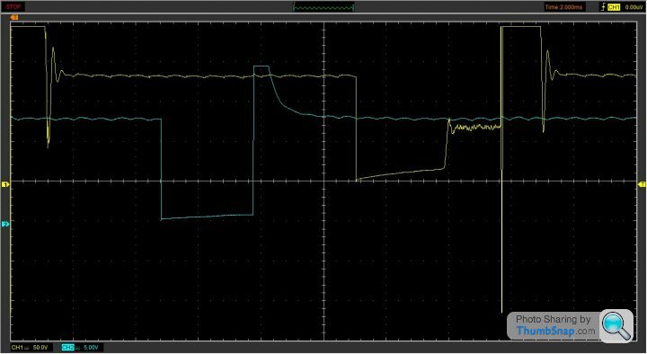
Re the 'scope screenshot, here's a simplified version. Yes the test was done at idle RPM, approx 1000. The x axis is time in mS (2 mS/vertical dotted line). The y axis in volts (Yellow trace is Ch 1 ignition coil/amplifier signal, using 50 V/horizontal dotted line); and blue Ch 2 the resultant injector pulse, using 5 V/horizontal line.
Edited by davep on Friday 25th June 21:33
davep said:
Re the 'scope screenshot, here's a simplified version. Yes the test was done at idle RPM, approx 1000. The x axis is time in mS (2 mS/vertical dotted line). The y axis in volts (Yellow trace is Ch 1 ignition coil/amplifier signal, using 50 V/horizontal dotted line); and blue Ch 2 the resultant injector pulse, using 5 V/horizontal line.
Hi DaveEdited by davep on Friday 25th June 21:33
This is obviously more complex than I first thought. Must admit when I looked at your first graphic I didn't realise there were faint dotted lines on it so thought you were referring to the small divisions actually on the axes. The X makes sense, in your latest graphic I'm seeing one complete cycle of an ignition event of around 16mS duration which calculates out to 937RPM.
What I'm more confused about is the Y axis, if this is 50v/division that indicates the signal spends most of it's time at high voltage, above 50V, I was not expecting that, where does this voltage come from? I was expecing to see a high voltage, short duration, spike just after the coil discharges but the rest of the time I was expecting to see somewhere between 0-14v or thereabout.
I'm presuming there must be some signal conditioning in the 14CUX which eventually boils this down to pulling the interupt pin to 0v when it 'sees' igntion occur, actually I don't imagine it needs to be timed exactly to ignition occuring all it really needs to do is pick out one point on that cycle, as long as it pickes the same point each time hence once and only once per ignition event that is all that matters as the fuelling is dependent on engine speed but not phase as injection isn't timed to any specific point in the cycle.
Unfortuanately I don't fully understand the requirment so I guess I'm going to have to leave this with linked to the coils with the diodes, I'll most likely end up frying something if I start connecting things together without more understanding.
If anyone has managed to trigger the 14CUX ignition signal from an ignition ECU tachometer output I'd be really pleased to hear about it and plagiarise where possible.
Optocoupler/ - isolator could provide a solution, see here:
https://wiki.autosportlabs.com/CoilX#:~:text=Getti...
or here for tacho input circuit:
http://www.megamanual.com/ms2/pcb.htm
https://wiki.autosportlabs.com/CoilX#:~:text=Getti...
or here for tacho input circuit:
http://www.megamanual.com/ms2/pcb.htm
Edited by davep on Monday 28th June 13:50
davep said:
Optocoupler/ - isolator could provide a solution, see here:
https://wiki.autosportlabs.com/CoilX#:~:text=Getti...
or here for tacho input circuit:
http://www.megamanual.com/ms2/pcb.htm
Thanks for that info' Dave.https://wiki.autosportlabs.com/CoilX#:~:text=Getti...
or here for tacho input circuit:
http://www.megamanual.com/ms2/pcb.htm
Edited by davep on Monday 28th June 13:50
It’s beginning to look like the only way I can create a signal to the 14CUX (apart from the diode to each coil) will involve creating some signal conditioning circuitry which kind of defeats the object of what I’m trying to achieve, or at least part of it.
I was looking into doing this for 2 reasons.
1) I don’t like having a piece of DIY circuitry in the system, it’s a likely point of failure.
2) It just more ‘elegant’ to have 2 ‘computers’ communicating via low voltage, controlled signals rather than one relying on a high voltage signal which appears to be “all over the place”.
Part of the problem is I have no idea what part of the “signal” the 14CUX is using as the trigger point and hence what the requirement of any signal I synthesise would be. A couple of things in particular have surprised me.
1) When disconnected the engine speed signal wire is at 12v, is seems really odd to me that a signal wire has voltage. I’m currently in the process of checking if this is a “problem” with my 14CUX or wiring although the system works without problem.
2) The voltage reading trace you’ve shown appears to show the signal spends most of its time at high voltage, and 3 distinct levels of this high voltage. 70V for around 1.2mS, 200v for around 1mS then 140v for around 10mS. I was expecting to see a short duration, high voltage “spike” just after what I think is the coil charge period (the 3mS duration ‘ramped’ part of the trace).
Do you know what is supplying the sustained higher voltage plateau of just over 10mS?
What ignition amplifier are you using? Maybe that is responsible.
With both of these areas unexplained I think it would be “dangerous” to continue with my quest. Although it’s a DIY solution I think remaining with the 4 diodes at least until I understand more would be more sensible. It also seems to be the “go to solution” and working well for most of the people most of the time. I just hate not understanding things!
CGCobra said:
Thanks for that info' Dave.
It’s beginning to look like the only way I can create a signal to the 14CUX (apart from the diode to each coil) will involve creating some signal conditioning circuitry which kind of defeats the object of what I’m trying to achieve, or at least part of it.
I was looking into doing this for 2 reasons.
1) I don’t like having a piece of DIY circuitry in the system, it’s a likely point of failure.
2) It just more ‘elegant’ to have 2 ‘computers’ communicating via low voltage, controlled signals rather than one relying on a high voltage signal which appears to be “all over the place”.
Part of the problem is I have no idea what part of the “signal” the 14CUX is using as the trigger point and hence what the requirement of any signal I synthesise would be. A couple of things in particular have surprised me.
1) When disconnected the engine speed signal wire is at 12v, is seems really odd to me that a signal wire has voltage. I’m currently in the process of checking if this is a “problem” with my 14CUX or wiring although the system works without problem.
2) The voltage reading trace you’ve shown appears to show the signal spends most of its time at high voltage, and 3 distinct levels of this high voltage. 70V for around 1.2mS, 200v for around 1mS then 140v for around 10mS. I was expecting to see a short duration, high voltage “spike” just after what I think is the coil charge period (the 3mS duration ‘ramped’ part of the trace).
Do you know what is supplying the sustained higher voltage plateau of just over 10mS?
What ignition amplifier are you using? Maybe that is responsible.
With both of these areas unexplained I think it would be “dangerous” to continue with my quest. Although it’s a DIY solution I think remaining with the 4 diodes at least until I understand more would be more sensible. It also seems to be the “go to solution” and working well for most of the people most of the time. I just hate not understanding things!
I originally did this test to prove the ignition pulse to injector firing relationship, 2 to 1. I didn't take much notice of the ignition pulse voltage waveform other than there is a pulse edge that triggers a fuelling interrupt.It’s beginning to look like the only way I can create a signal to the 14CUX (apart from the diode to each coil) will involve creating some signal conditioning circuitry which kind of defeats the object of what I’m trying to achieve, or at least part of it.
I was looking into doing this for 2 reasons.
1) I don’t like having a piece of DIY circuitry in the system, it’s a likely point of failure.
2) It just more ‘elegant’ to have 2 ‘computers’ communicating via low voltage, controlled signals rather than one relying on a high voltage signal which appears to be “all over the place”.
Part of the problem is I have no idea what part of the “signal” the 14CUX is using as the trigger point and hence what the requirement of any signal I synthesise would be. A couple of things in particular have surprised me.
1) When disconnected the engine speed signal wire is at 12v, is seems really odd to me that a signal wire has voltage. I’m currently in the process of checking if this is a “problem” with my 14CUX or wiring although the system works without problem.
2) The voltage reading trace you’ve shown appears to show the signal spends most of its time at high voltage, and 3 distinct levels of this high voltage. 70V for around 1.2mS, 200v for around 1mS then 140v for around 10mS. I was expecting to see a short duration, high voltage “spike” just after what I think is the coil charge period (the 3mS duration ‘ramped’ part of the trace).
Do you know what is supplying the sustained higher voltage plateau of just over 10mS?
What ignition amplifier are you using? Maybe that is responsible.
With both of these areas unexplained I think it would be “dangerous” to continue with my quest. Although it’s a DIY solution I think remaining with the 4 diodes at least until I understand more would be more sensible. It also seems to be the “go to solution” and working well for most of the people most of the time. I just hate not understanding things!
The test was done with a genuine Lucas DAB 113 Ignition Amplifier/Control module. Again I have not seen a schematic for this device.
Given that the pulse signal for pin 39 is taken from the negative side of a complex inductive load, I assumed the spike pulse in the trace was due to flyback, since the king lead side of the secondary winding is up in the kV range when pulsing. I was unable to find an example ignition coil waveform for negative terminal voltage conditions on the web to make a comparison, so I took what I saw as valid. It clearly shows the switching pulse to earth and the resultant flyback pulse, which satisfied the original requirement.
I agree that there will be filtering and probably inversion between pin 39 and pin 8 of the MPU. I have noticed that there is a Schmidt trigger NAND gate IC on the PCB.
14CUX switching convention states that "a 12V to 0V transition signifies On or energise".
Hi, I'm new here, just signed up to add some thoughts after reading through this rather large thread a few months ago.
My history is that I have a part built Land Rover conversion with a Range Rover 3.9EFI V8, using a 14CUX ECU that came with the engine. It starts and runs, though fuel pump doesn't suck enough fuel to do much more than 1200 RPM, but that's another problem.
I had not looked at it for some years, but got back to it a few months ago, and realised that now there was a lot of information about the 14CUX that I'd never seen before, particularly about re-mapping fuel tables and the ability to plug in a laptop via a modified serial port which sounded very useful.
Rather than risk damage to my existing 14CUX I thought it would be prudent to get a spare to play with, so a quick search on EBay and I found a 14CUX for £30. When it arrived I soon realised that all 14CUX's are not created equal, the cheap one I had was from an Austin Montego and not suitable to run a Rover V8. After studying the PCB layout I could see that there were component differences between them, but the PCB itself was very similar, enough to try to make it work I thought.
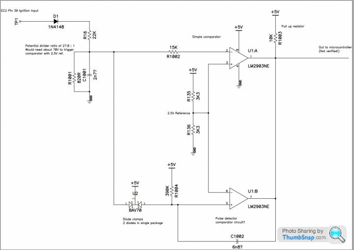
Adding the second injector bank driver was fairly easy, but the ignition input circuit was more of a challenge. I traced out the circuit from my Rover 14CUX and saw that it was some sort of voltage comparator and pulse forming circuit. Here is the circuit I traced out.
The top half of the circuit is a normal voltage comparator that would appear to flip state when a voltage pulse greater than about +70V was seen on the ignition input. The lower half of the circuit is a bit more unusual, it seems to be a pulse shaper maybe to ensure that each ignition pulse is only seen as a single event to the microcontroller interrupt pin, and not a multiple pulses from ignition noise.
Some of the capacitor values were best guesses after measuring with a cheap capacitor meter, which is why there's a question mark after those values. But that's what I soldered onto the board I have and the engine starts and ticks over without trouble.
Although my sketch says 'Out to microcontroller' I think I subsequently traced it going into the 74HC132 Schmitt NAND
If I wanted to feed a low voltage ignition signal directly into the 14CUX I would reduce the value of R16 from 22K to something like 1K8, which will put the trip voltage to about 8V instead of 70V. It's an easy thing to change and experiment with a suitable value to get it to work. Hope that helps.
My history is that I have a part built Land Rover conversion with a Range Rover 3.9EFI V8, using a 14CUX ECU that came with the engine. It starts and runs, though fuel pump doesn't suck enough fuel to do much more than 1200 RPM, but that's another problem.
I had not looked at it for some years, but got back to it a few months ago, and realised that now there was a lot of information about the 14CUX that I'd never seen before, particularly about re-mapping fuel tables and the ability to plug in a laptop via a modified serial port which sounded very useful.
Rather than risk damage to my existing 14CUX I thought it would be prudent to get a spare to play with, so a quick search on EBay and I found a 14CUX for £30. When it arrived I soon realised that all 14CUX's are not created equal, the cheap one I had was from an Austin Montego and not suitable to run a Rover V8. After studying the PCB layout I could see that there were component differences between them, but the PCB itself was very similar, enough to try to make it work I thought.
Adding the second injector bank driver was fairly easy, but the ignition input circuit was more of a challenge. I traced out the circuit from my Rover 14CUX and saw that it was some sort of voltage comparator and pulse forming circuit. Here is the circuit I traced out.
The top half of the circuit is a normal voltage comparator that would appear to flip state when a voltage pulse greater than about +70V was seen on the ignition input. The lower half of the circuit is a bit more unusual, it seems to be a pulse shaper maybe to ensure that each ignition pulse is only seen as a single event to the microcontroller interrupt pin, and not a multiple pulses from ignition noise.
Some of the capacitor values were best guesses after measuring with a cheap capacitor meter, which is why there's a question mark after those values. But that's what I soldered onto the board I have and the engine starts and ticks over without trouble.
Although my sketch says 'Out to microcontroller' I think I subsequently traced it going into the 74HC132 Schmitt NAND
If I wanted to feed a low voltage ignition signal directly into the 14CUX I would reduce the value of R16 from 22K to something like 1K8, which will put the trip voltage to about 8V instead of 70V. It's an easy thing to change and experiment with a suitable value to get it to work. Hope that helps.
davep said:
The test was done with a genuine Lucas DAB 113 Ignition Amplifier/Control module. Again I have not seen a schematic for this device.
Thanks for clarifying that. I had some weird idea that the ignition unit may be supplying the higher voltage, don't know why it would though.davep said:
Given that the pulse signal for pin 39 is taken from the negative side of a complex inductive load, I assumed the spike pulse in the trace was due to flyback...
That was my expectation too, however my expectation of a flyback 'spike' is different to what I see on your wave-form. I was expecting something like the form in the diagram labelled "Primary Ignition Waveform" about half way down this page:
http://www.g33.co.uk/pages/technical_ignition_syst...
Here I see the reading going from zero to a small voltage over 3mS (dwell period), followed by what I assume to be the flyback "spike", short duration up to 200v, holding more or less steady for around 1mS (spark duration I expect) then decaying back to 12v or so where the terminal is open circuit. The 12v being fed through the coil.
This is kind of what I was expecting but I may be mis-understanding what this diagarm is meant to represent.
davep said:
I was unable to find an example ignition coil waveform for negative terminal voltage conditions on the web to make a comparison, so I took what I saw as valid. It clearly shows the switching pulse to earth and the resultant flyback pulse, which satisfied the original requirement.
The link I put above may be what you are looking for.Which bit of your waveform are you seeing as the flyback? I was assuming the 200v level which holds for 1mS but I notice there is a drop below zero after that. On your original graphic this is seen on one cycle (the middle one) but not the firs or second. I was putting this down to a glitch in the reading but it could be that I'm simply reading this all wrong.
davep said:
I agree that there will be filtering and probably inversion between pin 39 and pin 8 of the MPU. I have noticed that there is a Schmidt trigger NAND gate IC on the PCB.
It's a while since I've been involved with electronics I need to do a bit of revision on the Schmidt trigger.davep said:
14CUX switching convention states that "a 12V to 0V transition signifies On or energise".
Totally agree which is why I'm so surprised by the presense of 12v on that wire. As I say, this may not be normall, could be an issue with my unit. Just because it is working doesn't mean it's working perfectly!Neil_Ward said:
Hi, I'm new here, just signed up to add some thoughts after reading through this rather large thread a few months ago.
My history is that I have a part built Land Rover conversion with a Range Rover 3.9EFI V8, using a 14CUX ECU that came with the engine. It starts and runs, though fuel pump doesn't suck enough fuel to do much more than 1200 RPM, but that's another problem.
I had not looked at it for some years, but got back to it a few months ago, and realised that now there was a lot of information about the 14CUX that I'd never seen before, particularly about re-mapping fuel tables and the ability to plug in a laptop via a modified serial port which sounded very useful.
Rather than risk damage to my existing 14CUX I thought it would be prudent to get a spare to play with, so a quick search on EBay and I found a 14CUX for £30. When it arrived I soon realised that all 14CUX's are not created equal, the cheap one I had was from an Austin Montego and not suitable to run a Rover V8. After studying the PCB layout I could see that there were component differences between them, but the PCB itself was very similar, enough to try to make it work I thought.
Adding the second injector bank driver was fairly easy, but the ignition input circuit was more of a challenge. I traced out the circuit from my Rover 14CUX and saw that it was some sort of voltage comparator and pulse forming circuit. Here is the circuit I traced out.
The top half of the circuit is a normal voltage comparator that would appear to flip state when a voltage pulse greater than about +70V was seen on the ignition input. The lower half of the circuit is a bit more unusual, it seems to be a pulse shaper maybe to ensure that each ignition pulse is only seen as a single event to the microcontroller interrupt pin, and not a multiple pulses from ignition noise.
Some of the capacitor values were best guesses after measuring with a cheap capacitor meter, which is why there's a question mark after those values. But that's what I soldered onto the board I have and the engine starts and ticks over without trouble.
Although my sketch says 'Out to microcontroller' I think I subsequently traced it going into the 74HC132 Schmitt NAND
If I wanted to feed a low voltage ignition signal directly into the 14CUX I would reduce the value of R16 from 22K to something like 1K8, which will put the trip voltage to about 8V instead of 70V. It's an easy thing to change and experiment with a suitable value to get it to work. Hope that helps.
Neil, your circuit and explanation is a great help. Good to see it works. I'd like to see your injector driver circuit diagram, if possible.My history is that I have a part built Land Rover conversion with a Range Rover 3.9EFI V8, using a 14CUX ECU that came with the engine. It starts and runs, though fuel pump doesn't suck enough fuel to do much more than 1200 RPM, but that's another problem.
I had not looked at it for some years, but got back to it a few months ago, and realised that now there was a lot of information about the 14CUX that I'd never seen before, particularly about re-mapping fuel tables and the ability to plug in a laptop via a modified serial port which sounded very useful.
Rather than risk damage to my existing 14CUX I thought it would be prudent to get a spare to play with, so a quick search on EBay and I found a 14CUX for £30. When it arrived I soon realised that all 14CUX's are not created equal, the cheap one I had was from an Austin Montego and not suitable to run a Rover V8. After studying the PCB layout I could see that there were component differences between them, but the PCB itself was very similar, enough to try to make it work I thought.
Adding the second injector bank driver was fairly easy, but the ignition input circuit was more of a challenge. I traced out the circuit from my Rover 14CUX and saw that it was some sort of voltage comparator and pulse forming circuit. Here is the circuit I traced out.
The top half of the circuit is a normal voltage comparator that would appear to flip state when a voltage pulse greater than about +70V was seen on the ignition input. The lower half of the circuit is a bit more unusual, it seems to be a pulse shaper maybe to ensure that each ignition pulse is only seen as a single event to the microcontroller interrupt pin, and not a multiple pulses from ignition noise.
Some of the capacitor values were best guesses after measuring with a cheap capacitor meter, which is why there's a question mark after those values. But that's what I soldered onto the board I have and the engine starts and ticks over without trouble.
Although my sketch says 'Out to microcontroller' I think I subsequently traced it going into the 74HC132 Schmitt NAND
If I wanted to feed a low voltage ignition signal directly into the 14CUX I would reduce the value of R16 from 22K to something like 1K8, which will put the trip voltage to about 8V instead of 70V. It's an easy thing to change and experiment with a suitable value to get it to work. Hope that helps.
Neil_Ward said:
.
The top half of the circuit is a normal voltage comparator that would appear to flip state when a voltage pulse greater than about +70V was seen on the ignition input. The lower half of the circuit is a bit more unusual, it seems to be a pulse shaper maybe to ensure that each ignition pulse is only seen as a single event to the microcontroller interrupt pin, and not a multiple pulses from ignition noise.
Although my sketch says 'Out to microcontroller' I think I subsequently traced it going into the 74HC132 Schmitt NAND
If I wanted to feed a low voltage ignition signal directly into the 14CUX I would reduce the value of R16 from 22K to something like 1K8, which will put the trip voltage to about 8V instead of 70V. It's an easy thing to change and experiment with a suitable value to get it to work. Hope that helps.
Hi Neil, apologies, didn’t see your response earlier. Sounds like you’ve done some good and interesting work there.The top half of the circuit is a normal voltage comparator that would appear to flip state when a voltage pulse greater than about +70V was seen on the ignition input. The lower half of the circuit is a bit more unusual, it seems to be a pulse shaper maybe to ensure that each ignition pulse is only seen as a single event to the microcontroller interrupt pin, and not a multiple pulses from ignition noise.
Although my sketch says 'Out to microcontroller' I think I subsequently traced it going into the 74HC132 Schmitt NAND
If I wanted to feed a low voltage ignition signal directly into the 14CUX I would reduce the value of R16 from 22K to something like 1K8, which will put the trip voltage to about 8V instead of 70V. It's an easy thing to change and experiment with a suitable value to get it to work. Hope that helps.
Thanks for the input
Need to have a good look at your diagram and work out what’s going on but interesting that you mention the trigger occurring at a specific voltage threshold, that makes sense.
Looks like I’ll need to make internal mod’s as you suggest if I want to trigger with a low voltage signal.
Looking at the diagram leaves me confused about the voltage I’m seeing on the black/white line it’s making me suspect even moreso that I may have an issue there. Need to check that out.
davep said:
Neil, your circuit and explanation is a great help. Good to see it works. I'd like to see your injector driver circuit diagram, if possible.
Hi,I hadn't traced the injector driver part out, but give me a few days and I'll try and get it done and post results here. I'll also update the comparator circuit too as I notice I've got some of the part designators wrong, which won't help! Some of the resistors and the BAV70 dual diode are surface mount components on the underside of the PCB, so don't have printed designators. I just tagged them as 1000's numbers on my drawing.
From memory it was the microcontroller outputs to the ULN2803 octal transistor drivers (chips I5 and I6), which then drive the NPN Darlington output transistors. The part numbers were obfuscated on the transistors, so I chose a BDX53B which should easily cope with the injector coil current, bought from here:
https://uk.farnell.com/stmicroelectronics/bdx53b/d...
Injector coils are wired to one side to positive supply, and the NPN Darlingtons in the ECU pull the other side to negative to fire the injector. There is also a 2u2 100V rated capacitor in each injector driver, probably to quench the injector coil flyback voltage while allowing a reasonably fast turn off.
I also remembered that when I was testing the ignition input circuit I hacked on a lower value resistor to the input and drove it from a 12V pulse from a signal generator on my bench. A couple of LEDs wired in place of each injector output told me when I'd got it working. It was a nasty wiring lash up, but proved that it was working before trying it on the vehicle. It took me a few attempts to get it right, as I guessed wrongly that the transistors were just NPN and not NPN Darlingtons with some other integrated components. So it can easily be made to work from 12V (or lower if you like) ignition timing pulses.
Hi Neil,
I'm also a 14CUX enthusiast. Your ignition schematic is brilliant work. I also traced out the circuit a few years ago and I'm embarrassed to say that I got some things wrong and the circuit never made complete sense to me until now. I should have gone back and rechecked my tracing work but I find it very tedious and, at the time, I was focused more on the software. Seeing your correct schematic was very satisfying.
I did notice the discrepancy in the part designators, so I'm glad you pointed that out in your 2nd post. You are also correct about the output of the comparators going to the Schmitt NAND (I3). It then goes through an inversion at I14 which is a plain vanilla NAND (7400). The output of I14 (pin 11) goes to pin 8 of the microprocessor. This triggers an interrupt in the software.
Since I didn't understand the circuit until now, when I was bench testing of the 14CUX I ran the output of my pulse generator through a transformer to get enough voltage to trigger the circuit. Shunting down the input resistor makes a lot more sense.
Hi,
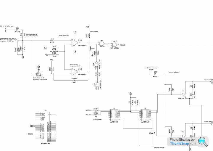
I've traced a bit further on the ignition input circuit, as well as the injector drive outputs for those interested, hope you can see the JPG OK. Beware it may not be 100% accurate!
I'm still in the process of tracing the TTL logic parts, as they seem to have some sort of signal gating for the ignition pulse maybe, shown as chip I3 gates 2 and 4. Perhaps once an ignition pulse has been detected it blanks out the signal to the MCU for a period of time to prevent noise giving extra false triggering.
The conformal coating on the PCB makes it difficult to trace as easily as uncoated PCBs. Also the PCB layout adds some confusion too, it's not the most logical of component layouts or trace routing to put it politely.
More to come as I get chance... it sure is tedious though!
Neil_Ward said:
Hi,
....
More to come as I get chance... it sure is tedious though!
Neil, welcome to the world of demystifying 14CUX!....
More to come as I get chance... it sure is tedious though!
Many thanks for doing this circuit tracing work, it'll help fill in many missing links.
Hi Dan, good to see you back, hope all is well with you and Colin.
Re the injector driver circuit and the swapping of injector types. What differences, if any, do injector characteristics (inductance and reactance) make on the driver load circuit's current and voltage levels and injector coil operation, since some injectors are designed to work in parallel groups (1/LT = 1/L1+ 1/L2 ...) and some as single in series (LT = L1).
davep said:
Neil, welcome to the world of demystifying 14CUX!
Many thanks for doing this circuit tracing work, it'll help fill in many missing links.
I'll second that, a fantastic piece of work. Many thanks for doing this circuit tracing work, it'll help fill in many missing links.
I still don't fully understand it but at least I know that it is high (way above 12v) voltage which instigates the signal so there is nothing I can do outside of the box.
I could swap out the resistor as you've advised but then my 14CUX is non-standard and I have a couple of these (and then some!) which I like to be able to swap around so I'd have to modify both/all of my 14CUX's
davep said:
Hi Dan, good to see you back, hope all is well with you and Colin.
I'll second that too.davep said:
Neil, welcome to the world of demystifying 14CUX!
Many thanks for doing this circuit tracing work, it'll help fill in many missing links.
Good to know it may be of some use to others, I'll keep going if I'm not annoying folks with my electronic ramblings.Many thanks for doing this circuit tracing work, it'll help fill in many missing links.
I did find a little more since my last post, the Schmitt NAND circuit I was tracing is incorrect, it now looks like it's simply gated with the MPU RESET (pin 6) so that there's a short delay after reset that stops ignition pulses reaching the MPU after power up. I'll update the drawing and perhaps write some more detailed explanation of how I think it all works.
davep said:
Re the injector driver circuit and the swapping of injector types. What differences, if any, do injector characteristics (inductance and reactance) make on the driver load circuit's current and voltage levels and injector coil operation, since some injectors are designed to work in parallel groups (1/LT = 1/L1+ 1/L2 ...) and some as single in series (LT = L1).
Now that's an interesting can of worms to open...I have not measured my injector coil inductance (yet!), I think on my Rover V8 engine it's two banks of 4 injectors, with the 4 wired in parallel. That would reduce total inductance but increase drive current, I guess for faster turn on/off compared with coils 4 in series.
The drive circuit itself looks fairly simple as an NPN Darlington with an RC snubber in parallel (the 15R resistor and 2u2 capacitor) to quench any high voltage spikes. The BD53B I'd chosen for my hacked circuit also has an integrated body flyback diode from collector to emitter (not shown on the component symbol). I really should check that the original transistor also has this diode, as if it's missing then it could mean there's a big difference in injector turn off time from the real Rover 14CUX and my hacked Austin 14CUX PCB.
The body diode means that the injector coil current will decay more slowly than if it were not there, so the injector would remain open for slightly longer.
I suspect that actual turn on and off times are not too important in a petrol ECU compared to the much more critical diesel injectors. It's only after reading this thread I learned that the injectors fire on each ignition pulse and are not synchronised to the individual cylinders, so are delivering fuel even when an inlet valve is closed!
If I can get a reading of the injector inductances we could calculate some typical turn on an turn off times, would be interesting to see just what sort of times they are.
To get fast turn on/off on injector coils, you need to hit them with a high voltage to drive them open, and allow a large flyback voltage to build as they turn off, and try to keep inductance to a minimum. Diesel ECU's have voltage boosters in them for this reason, a much more complex injector drive circuit than the 14CUX.
Neil_Ward said:
Good to know it may be of some use to others, I'll keep going if I'm not annoying folks with my electronic ramblings.
Keep rambling Neil!Neil_Ward said:
I did find a little more since my last post, the Schmitt NAND circuit I was tracing is incorrect, it now looks like it's simply gated with the MPU RESET (pin 6) so that there's a short delay after reset that stops ignition pulses reaching the MPU after power up. I'll update the drawing and perhaps write some more detailed explanation of how I think it all works.
Dan explained this 'dual functionality' some time back, the three Port 2 lines P20, P21, P22 during MPU RESET are used to define the Mode Select Logic. Once out of RESET the lines are used as data in/out lines, where P20 carries the ignition pulse edge of course. See page 31.Neil_Ward said:
... lots of interesting info ... It's only after reading this thread I learned that the injectors fire on each ignition pulse and are not synchronised to the individual cylinders, so are delivering fuel even when an inlet valve is closed!
Although an interrupt, IRQ2, is issued for every ignition pulse, control logic, in the main, toggles the interrupt type between 'fuelling' and 'non-fuelling', this results in an injector firing for every other ignition pulse. Control logic then alternates the injector firings between the left and right bank.Gassing Station | Griffith | Top of Page | What's New | My Stuff