Instructions to change fuel maps on 14CUX Griffith, Chimaera
Discussion


Looking at the run data for OP's run out with fixed thermostat everything on RG is looking a normal apart from.....more on that in a moment.
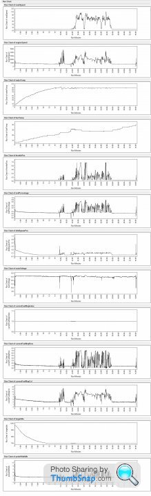
Looking at "Steady state" section (which I need for determining if the MAF etc is performing correctly) between 39 to 43 minutes.the individual components all look good, especially the MAF with Std Dev of 0.0025 (Good MAF's are less than 0.05 Bad ones > 0.07)
The odd bit is that the System voltage at the start of steady state runs at 12.9 then after a minute jumps to 13.1 which seems to impact
1. MAF
2. Fuel MAP row and column
3. Pulse width
4. and maybe Throttle position
stevesprint said:
If you can get your AFR log to look like this you can then use my RG & AFR log merger program or merge the logs on Excel.
2023-06-14_15:05:58.871,13.6
2023-06-14_15:05:58.964,13.5
2023-06-14_15:05:59.042,13.5
2023-06-14_15:05:59.120,13.5
2023-06-14_15:05:59.214,13.5
2023-06-14_15:05:59.292,13.5
2023-06-14_15:05:59.370,13.5
2023-06-14_15:05:59.448,13.7
Your Row Scalar sounds correct as you’re reaching the bottom of the fuel table so just focus on the main multipier.
I can have a go at getting the AFR data log to match that data layout. Will let you know2023-06-14_15:05:58.871,13.6
2023-06-14_15:05:58.964,13.5
2023-06-14_15:05:59.042,13.5
2023-06-14_15:05:59.120,13.5
2023-06-14_15:05:59.214,13.5
2023-06-14_15:05:59.292,13.5
2023-06-14_15:05:59.370,13.5
2023-06-14_15:05:59.448,13.7
Your Row Scalar sounds correct as you’re reaching the bottom of the fuel table so just focus on the main multipier.
blaze_away said:
Looking at the run data for OP's run out with fixed thermostat everything on RG is looking a normal apart from.....more on that in a moment.
The odd bit is that the System voltage at the start of steady state runs at 12.9 then after a minute jumps to 13.1 which seems to impact
1. MAF
2. Fuel MAP row and column
3. Pulse width
4. and maybe Throttle position
Maybe caused by the alternator switching in. I can't think of anything else that would cause a sustained increase in voltage like that.The odd bit is that the System voltage at the start of steady state runs at 12.9 then after a minute jumps to 13.1 which seems to impact
1. MAF
2. Fuel MAP row and column
3. Pulse width
4. and maybe Throttle position
SteveSprint you need to fit a steering column!
Adam
I’ve worked out in Excel how to add the system time with millisec to your AFR readings with the following, I'll email you the spreadsheet.
Column B = TIME(15,23,32+A5)
Column C = IF(LEFT(RIGHT(A5,2),1)=".",CONCATENATE(RIGHT(A5,1),"00"),CONCATENATE(RIGHT(A5,2),"0"))
Column D = CONCATENATE("2023-06-12_",TEXT(B5,"hh:mm:ss"),".",C5)
However your start time doesn’t contain millisecs and therefore could be out upto 0.9 sec, nevertheless I'll have a go merging the logs you've emailed with your fixed thermostat.
Drive smoothly & steadily while logging with no sudden throttle movements otherwise the throttle enrichment will skew the AFR.
Strange your TunerPro won't update the checksum, I assume the fuel tables load & look ok, what version are you running?
Don’t worry about the checksum fault code in RoverGauge its harmless and simply means your checksum is wrong.
You could always correct your checksum with www.remap-14cux.uk/software/14CUX_Toolkit_V1-2.exe
Good Luck and data log safely
Edited by stevesprint on Saturday 17th June 23:01
stevesprint said:
Adam
I’ve worked out in Excel how to add the system time with millisec to your AFR readings with the following, I'll email you the spreadsheet.
Column B = TIME(15,23,32+A5)
Column C = IF(LEFT(RIGHT(A5,2),1)=".",CONCATENATE(RIGHT(A5,1),"00"),CONCATENATE(RIGHT(A5,2),"0"))
Column D = CONCATENATE("2023-06-12_",TEXT(B5,"hh:mm:ss"),".",C5)
However your start time doesn’t contain millisecs and therefore could be out upto 0.9 sec, nevertheless I'll have a go merging the logs you've emailed with your fixed thermostat.
Drive smoothly & steadily while logging with no sudden throttle movements otherwise the throttle enrichment will skew the AFR.
Strange your TunerPro won't update the checksum, I assume the fuel tables load & look ok, what version are you running?
Don’t worry about the checksum fault code in RoverGauge its harmless and simply means your checksum is wrong.
You could always correct your checksum with www.remap-14cux.uk/software/14CUX_Toolkit_V1-2.exe
Good Luck and data log safely
Awesome stuff. Thank you. I’ve worked out in Excel how to add the system time with millisec to your AFR readings with the following, I'll email you the spreadsheet.
Column B = TIME(15,23,32+A5)
Column C = IF(LEFT(RIGHT(A5,2),1)=".",CONCATENATE(RIGHT(A5,1),"00"),CONCATENATE(RIGHT(A5,2),"0"))
Column D = CONCATENATE("2023-06-12_",TEXT(B5,"hh:mm:ss"),".",C5)
However your start time doesn’t contain millisecs and therefore could be out upto 0.9 sec, nevertheless I'll have a go merging the logs you've emailed with your fixed thermostat.
Drive smoothly & steadily while logging with no sudden throttle movements otherwise the throttle enrichment will skew the AFR.
Strange your TunerPro won't update the checksum, I assume the fuel tables load & look ok, what version are you running?
Don’t worry about the checksum fault code in RoverGauge its harmless and simply means your checksum is wrong.
You could always correct your checksum with www.remap-14cux.uk/software/14CUX_Toolkit_V1-2.exe
Good Luck and data log safely
Edited by stevesprint on Saturday 17th June 23:01
The weather is shocking at the moment. 6C and sleet. Haven't had a chance to get the car out.
Once it clears up I'll go for some smooth runs.
Thank you all for your great help, the initial changes to the main table scalar have gotten the car driveable. Still a bit rich. But once I get a couple of runs and some logging I'll look to correct the fuel table.
Adam, I‘ve merged and emailed your logs, we can carry on via email.
Adam and for the benefit of others, if you stop logging all parameters in RoverGauge you'll capture more records per seconds. For example turn off water & fuel temps, voltage, currentFuelMapIndex, target idle & lambda etc.
Enjoy, Weather permitting
Adam and for the benefit of others, if you stop logging all parameters in RoverGauge you'll capture more records per seconds. For example turn off water & fuel temps, voltage, currentFuelMapIndex, target idle & lambda etc.
Enjoy, Weather permitting
AllanWorms said:
- Can I use the factory O2 sensors to acheive better fuel economy, rather than cat efficiency? My current understanding is that I can lean out the fuel table for low RPM and load, but the O2 sensors will try to alter the trims to run it at stoich - I'm not sure the system is complex enough to do it much better though?
I have no Cats, so could run better economy on the Lambda feedback, then have the fuelling tables take over for higher load and RPM areas of the fuel map? "Cruise" situations could have better economy then?
So in theory, for gentle driving, the lambdas would lean out the fuel, but over taking or towing would result in the lambda having less influence, such as over 3400 RPM and high throttle inputs? can I change the code to do that?
Thanks
Hi all
Unfortunatly been away for a while due to other aspects of life taking over! I've just got back on to this and I can see that things have slowed down somewhat, just wondering if anyone is still around who could help out with as question on the workings of the 6803 processor, I'm particularly interested in the memory map and how it handles Internal/External memory around the $80-FF range (which includes the battery backed part)?
Unfortunatly been away for a while due to other aspects of life taking over! I've just got back on to this and I can see that things have slowed down somewhat, just wondering if anyone is still around who could help out with as question on the workings of the 6803 processor, I'm particularly interested in the memory map and how it handles Internal/External memory around the $80-FF range (which includes the battery backed part)?
CGCobra said:
Hi all
... the memory map and how it handles Internal/External memory around the $80-FF range (which includes the battery backed part)?
See Dan's Assembler source build file ramLocations.asm and the MC6083UA data sheet figure 16 - Mode 2. The addresses are used to hold the variables and condition bits that are read and written to by the respective routines during run time.... the memory map and how it handles Internal/External memory around the $80-FF range (which includes the battery backed part)?
The variables in the $0080 - FF locations are:
uncompFuelInjValue = $0080 ;* 16-bit, in process, both banks
compedFuelInjValue = $0082 ;* 16-bit, final injector value, exc. for Lambda trim
timer1value = $0084 ;* used for 1 Hz countdown timer 1
bits_0085 = $0085 ; used as condition bits
bits_0086 = $0086 ; used as condition bits
bits_0087 = $0087 ; used as condition bits
bits_0088 = $0088 ; used as condition bits
bits_0089 = $0089 ;* used as condition bits
bits_008A = $008A ; used as condition bits
bits_008B = $008B ; used as condition bits
bits_008C = $008C ;* used as condition bits
bits_008D = $008D ;* used as condition bits
iciValueEven_8E = $008E ; used in ICI (indexed, do not move)
iciValueOdd_8F = $008F ; used in ICI (indexed, do not move)
iciValue90 = $0090 ; used in ICI (indexed, do not move)
iciValue91 = $0091 ; used in ICI (indexed, do not move)
iciValue92 = $0092 ; used in ICI (indexed, do not move)
iciValue93 = $0093 ; used in ICI (indexed, do not move)
iciValue94 = $0094 ; used in ICI (bank related)
iciValue95 = $0095 ; used in ICI (bank related)
purgeValveTimer = $0096 ;*(R) 16-bit, purge value related
purgeValveTimer2 = $0098 ;* 16-bit, purge valve related
purgeValveValue = $009A ;* purge valve related
crankingFuelValue = $009B ;x value from 2nd row of 3 x 12 table, value is static
startupFuelTime = $009C ;x value from 3rd row of 3 x 12 table, decrements at 1 Hz rate
doubleInjecterRate = $009D ;* 16-bit, normally 192, number of sparks for double fuel rate (todo: reduce to 1-byte)
hotFuelAdjustmment = $009F ;* 16-bit, probably the fuel adjustment for startup w/hot underhood temp
fuelTempCounter = $00A1 ;* a counter used in the fuel temperature service routine
unused1 = $00A2 ;* (unused)
unused2 = $00A3 ;* (unused)
savedThrottlePot = $00A4 ;* 16-bit, saved TPS value (only when closing) in TPS service routine
injectorPulseCntr = $00A6 ;* counter for injector micropulses during very cold startup
startupCodeDelay = $00A7 ;* counter for small startup code execution delay
bits_00A8 = $00A8 ;* bits 7 and 0 only used in one routine
bankValue1 = $00A9 ; 16-bit, used as bank related value
bankValue2 = $00AB ; 16-bit, used as bank related value
iacvAdjustSteps = $00AD ;* rate of adjustment steps for IACV motor
iacvWorkingValue = $00AE ;* the working or in-process value for the stepper motor adjustment
fuelPumpTimer = $00AF ;*(W) write only, init to 255, decr in main, renewed in ICI, zero shuts off pump
ectCounter = $00B0 ;* used as a counter in the ECT service routine
inertiaCounter = $00B1 ;* used as counter in inertia switch service routine
timerOverflow1 = $00B2 ;* timer overflow counter
idleSpeedDelta = $00B3 ;* difference between target idle and actual RPM
idleSpeedCounter = $00B4 ;* counter used for idle control
idleControlValue = $00B5 ;* 16-bits, a signed value used for idle control
unused3 = $00B7 ;* (unused)
acDownCounter = $00B8 ;* a counter used for A/C compressor control
adcReadingUnused = $00B9 ;* 16-bit, ADC reading is stored here but not used
rsFaultSlowdown = $00BB ;* 16-bit, a slowdown counter used for VSS fault
workingBankValue = $00BD ; the working (in process) value for X008E or X008F
bankRelatedValue1 = $00BE ; bank value
bankRelatedValue2 = $00BF ; bank value
idleRelatedValue = $00C0 ;* an idle related value
tpsClosedLoopCntr = $00C1 ;* increments to 19, can be cleared or reset to $FF
tpsTimer = $00C2 ;* 16-bit, a timer used to measured throttle rate
sparkPeriodTimer = $00C4 ;* 16-bit, timer value saved near start of ICI to measure spark period
stepperMotorTimer = $00C6 ;* 16-bit, timer value used to pace stepper motor control signals
generalPurpose0 = $00C8 ; 16-bit
generalPurpose1 = $00CA ; 16-bit
generalPurpose2 = $00CC ; 16-bit
generalPurpose3 = $00CE ; 16-bit
counter16bit = $00D0 ; 16-bit, used as two 8-bit values in older (TVR) code
bits_00D2 = $00D2 ;
bits_00D3 = $00D3 ;
bankCounterLeft = $00D4 ;
bankCounterRight = $00D5 ;
dualNibbleCounter = $00D6 ;
unused4 = $00D7 ;
unused5 = $00D8 ;
savedTpsValue = $00D9 ;* 16-bit, saved TPS value from last call
purgeValveCounter = $00DB ;*
bits_00DC = $00DC ;
bits_00DD = $00DD ;
unused6 = $00DE ;
groupFaultCounter = $00DF ;* counter used in group code area
misfireCounterEven = $00E0 ;*
misfireCounterOdd = $00E1 ;*
bits_00E2 = $00E2 ; indicates TPS is 30% and ECT cooler than 50 C
throttlePotTemp = $00E3 ;* 16-bit, temporary storage of TPS value
sciIndex1 = $00E5 ;
sciIndex2 = $00E6 ;
sciCounter = $00E7 ;
sciRcvChar = $00E8 ;
sciXmtPtr = $00E9 ; 16-bit
sciIndex3 = $00EB ; 16-bit
sciIndex4 = $00ED ; 16-bit
; (stack area)
topOfStack = $00FF ; top of MPU stack
davep said:
See Dan's Assembler source build file ramLocations.asm and the MC6083UA data sheet figure 16 - Mode 2. The addresses are used to hold the variables and condition bits that are read and written to by the respective routines during run time.
Thanks Dave as always. That is some of the data which I am looking at however I found what appeared to be an issue in the reset.asm file where the battery backed memory is checked and various memory locations are cleared. Later on last night I delved into the program which checks the BB RAM and found that this is looking at a different area than I was expecting also. This told me that my expectations are wrong!Problem is I'm working from a number of sources for the M6803 processor, thought using the latest manual was the way to go but turns out that although this covers 60803 it is not the U4 instance, found the datasheet for this amongst Dan B's documentation and can see that this has a different memory map with a smaller BB section starting at an earlier address, now it all makes sense.
I've also just found some additional data on Colin's web site which has helped greatly.

CGCobra said:
... I delved into the program which checks the BB RAM and found that this is looking at a different area than I was expecting also. This told me that my expectations are wrong!
...this has a different memory map with a smaller BB section starting at an earlier address, now it all makes sense.
CG where in the 'program' was this check of BB RAM done?...this has a different memory map with a smaller BB section starting at an earlier address, now it all makes sense.
You probably already know this, but to verify: the Battery Backed parameters are written to two areas of RAM, one internal version and one external in the PAL IC.
Internal:
secondaryLambdaR = $0040 ; used during lambda calculations
longLambdaTrimR = $0042 ; (R) 16-bit, long term trim
secondaryLambdaL = $0044 ;
longLambdaTrimL = $0046 ; (R) 16-bit, long term trim
hiFuelTemperature = $0048 ;
faultBits_49 = $0049 ;x(R)
faultBits_4A = $004A ;x(R)
faultBits_4B = $004B ;x(R)
faultBits_4C = $004C ;x(R)
faultBits_4D = $004D ;x(R)
faultBits_4E = $004E ;x(R)
stprMtrSavedValue = $004F ;x related to stepper motor and saved in battery backed memory
fuelMapNumberBackup = $0050 ;
throttlePotMinimum = $0051 ; (R) 16-bit
throttlePotMinCopy = $0053 ;
ramChecksum = $0053 ; note that this location is used twice
External PAL RAM:
Parameters and sequence as above but at $2060. - $2072.
davep said:
CG where in the 'program' was this check of BB RAM done?
You probably already know this, but to verify: the Battery Backed parameters are written to two areas of RAM, one internal version and one external in the PAL IC.
Not actually got that far yet. I was working form the top down so started looking at reset.asm. Unfortunately I don't have the file with me at the moment but there is a section in there which clears the internal memory, based on the address it was starting at I thought it was going to clear the battery backed area, this was based on the manual I had read indicating Internal RAM starting address as $0080 and the BB section being 64 bytes starting at the top of this running to $00BF. You probably already know this, but to verify: the Battery Backed parameters are written to two areas of RAM, one internal version and one external in the PAL IC.
Having now gone through more of the program I realised that several areas were indicating that this was wrong so I dug out some furhter PDFs and found that 'our' version of the processor has Internal RAM starting at $0040 and the battery backed section being 'only' 32bytes (of which we only use 20). Now it all makes sense as the section whcih is cleared starts at $0054 which is immediately after the 20bytes of BB RAM.
Not got to the bit about having a copy of this section in a different area but I do recall reading something about that previously.
Great to see you're still active on this by the way.
Amazing to see how busy this topic still is.
One of the things that has always got me is the AFM, I have been using the Bosch 0 280 218 010 meter with the remap but as we know the MAF curve is a fair bit different than the 5AM. (I am running a range rover classic not a grif...... and pushing 3 tonnes with everything on it)
This is the chart comparing the two meters: (I also have ADC counts if anyone is interested)
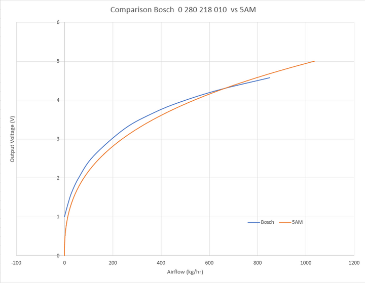
I have spent a lot of time in the rebuild code looking at the MAF related code and the interactions with it in the system as a whole. I am slowing working through how it uses the readings from the airflow meter. In the mean time I have created a little airflow converter that takes in the signal from the bosch and maps that to the equivalent signal of the 5AM. My setup is running the fuel rail at 3.5bar with EV6 injectors (4 hole spray), using a GEMS system plenum top with a 200 count air idle control stepper motor (code modified from the 180 count).
I just ran some test today with it (of course with new base maps) and I do think the car runs better. I use to find at the top end the car would get flat and I believe that this is because the bosch curve flattens out at the top end, how the 14CUX linearises the curve and uses it for load indexing it appears the load is reducing. When comparing the linearised MAF load with and without the airflow converter, the MAF load is higher at idle and in lower throttle positions. Once corrected the MAF loading is reduced for lower loads and increased for higher loads.
Overall I find the car much more responsive with a smoother idle when hot (I have kept throttle maps, coolant table etc the same and only changed the relevant fuel maps and scalars). Based on what I understand (which is limited) from the code and what I have seen today I do believe that while the 14CUX can be made to work with the bosch directly it is not particularly ideal and actually makes the system run sub-optimal.
My ultimate goal would be to modify the rebuild project to natively use the bosch meter, that is the linearisation of the MAF and its load indexing is correct for the airflow, so I am slowly chipping away at this.
Has anyone else looked at this? I am also be interested in the thoughts from the people that have spent a lot of time in the rebuild code and have spent many hours tuning the 14CUX.
Also as a side note using chatGPT for working through code sections is really a big help.
Cheers,
Josh
One of the things that has always got me is the AFM, I have been using the Bosch 0 280 218 010 meter with the remap but as we know the MAF curve is a fair bit different than the 5AM. (I am running a range rover classic not a grif...... and pushing 3 tonnes with everything on it)
This is the chart comparing the two meters: (I also have ADC counts if anyone is interested)
I have spent a lot of time in the rebuild code looking at the MAF related code and the interactions with it in the system as a whole. I am slowing working through how it uses the readings from the airflow meter. In the mean time I have created a little airflow converter that takes in the signal from the bosch and maps that to the equivalent signal of the 5AM. My setup is running the fuel rail at 3.5bar with EV6 injectors (4 hole spray), using a GEMS system plenum top with a 200 count air idle control stepper motor (code modified from the 180 count).
I just ran some test today with it (of course with new base maps) and I do think the car runs better. I use to find at the top end the car would get flat and I believe that this is because the bosch curve flattens out at the top end, how the 14CUX linearises the curve and uses it for load indexing it appears the load is reducing. When comparing the linearised MAF load with and without the airflow converter, the MAF load is higher at idle and in lower throttle positions. Once corrected the MAF loading is reduced for lower loads and increased for higher loads.
Overall I find the car much more responsive with a smoother idle when hot (I have kept throttle maps, coolant table etc the same and only changed the relevant fuel maps and scalars). Based on what I understand (which is limited) from the code and what I have seen today I do believe that while the 14CUX can be made to work with the bosch directly it is not particularly ideal and actually makes the system run sub-optimal.
My ultimate goal would be to modify the rebuild project to natively use the bosch meter, that is the linearisation of the MAF and its load indexing is correct for the airflow, so I am slowly chipping away at this.
Has anyone else looked at this? I am also be interested in the thoughts from the people that have spent a lot of time in the rebuild code and have spent many hours tuning the 14CUX.
Also as a side note using chatGPT for working through code sections is really a big help.
Cheers,
Josh
Hi Josh
I need to look at what you're doing in a bit more detail (midnight on a Friday is not the best time!) but it looks interesting.
I'm also currenlty dredging through the code to work out how the 14CUX goes about it's job, it's time consuming and I keep getting dragged off onto other projects.
I'm interested in your comment about using AI to work through the code, may have to look into that myself.
Gassing Station | Griffith | Top of Page | What's New | My Stuff