Professional help needed
Discussion


Hi so I have been rebuilding a griffith 500. I was hoping to start the car yesterday for the first time.
So every single wire has been out of the car as part of the rebuild and put back in, bare this in mind, I have been able to insert the key and turn over the engine since I had everything fitted to the engine etc. It's turned over fine in the last month or so. Which is great.
So the issue arose yesterday, I fitted exhaust. So the only thing I needed to do was put fuel in and fill with coolant.
So started filling up the fuel tank, got around 10L in. Thought I would prime the pump and check there were no leaks. So stuck the key in and turned it to the last position before you make the final turn to fire the engine. The pump did NOT prime. Tried several things, to get the pump to prime I have had no luck. So thought maybe it would prime if I tried turning over the engine so turned the key to the final position and the engine would not turn over.
So I've not experienced that prior to yesterday, as the engine has always turned over. I was thinking back and I don't think I have heard the pump prime at all while I've had the ignition on checking things say like Windows up and down and mirrors moving etc. To be honest I was not looking out for it either. If you see what i mean.
Anyway done a load of checking tonight and what I have found and fixed is 2 relays were not working 1 was the blue fuel pump relay. I have replaced those and it has made no difference.
I can remove the immobiliser block which contains the two white and red stripe wires (ignition to starter motor) and two yellow black wires (fuel pump). I hope your still with me.
Ok if I joint the two white red with a wire. Engine turns over with the key. If I joint the two yellow and black, the pump does NOT fire up. So there is something with the fuel pump there I cannot figure out, I think the main issue here is the immobiliser but what I can't figure out is why the fuel pump won't prime when jointing these 2 wires.
Anyway so to check everything is fine to the fuel pump I shorted a positive direct to one of the two yellow black wires. Boom pump primed up when I took live direct to one of the 2 yellow and black wires. When I shorted the other yellow and black wire... Oddly I got a click from the engine area. After a bit of investigation this is the carbon canister clicking...
So my question is this. Where does the fuel pump wire originate from? Where does it go and I know where it ends up. So from the connector block I shorted, I know the wire goes from there to the inertia switch then fuel pump. So on the opposite, I know the wire goes back to carbon can, where else does it come from? Goto?
I have seen the blue relay block, but yellow and black wires are not there I have purple and black.?? Where do they come and go from. Where do they turn yellow and black. There is no power to the relay. Which is why there is no power to the pump at the connector block.
I'm not sure if these are controlled by the immobiliser?
I'm only asking as I have a friend auto electrician coming on Saturday and he is ripping out the current alarm immobiliser and fitting a clifford unit. I just want to be sure everything is correct prior to this so i can ensure the car will fire into life when the alarm is swapped. Alot of information here but if someone is able to pass on some insight that maybe helpful.
Thank you!
Ok this is what i was thinking, so fuel pump is started by the relay from the Ecu. But it must go via the immobiliser first. This is the bit I'm missing which wire will it be. 
Yeah I've got the alarm and clicked it after the key is in the primary position and locked and unlocked it before putting the key in.
Yeah I've got the alarm and clicked it after the key is in the primary position and locked and unlocked it before putting the key in.
Got a guy coming on Saturday. He has said he'd prefer if the car was running first. Makes sense. I'm going to spend a bit of time on the car tonight. I have the wiring diagram in the bible. What I can't get my head around is the wires go into a block... Then where to? This info would help plenty.
Mike8448 said:
Hi so I have been rebuilding a griffith 500. I was hoping to start the car yesterday for the first time.
So every single wire has been out of the car as part of the rebuild and put back in, bare this in mind, I have been able to insert the key and turn over the engine since I had everything fitted to the engine etc. It's turned over fine in the last month or so. Which is great.
So the issue arose yesterday, I fitted exhaust. So the only thing I needed to do was put fuel in and fill with coolant.
So started filling up the fuel tank, got around 10L in. Thought I would prime the pump and check there were no leaks. So stuck the key in and turned it to the last position before you make the final turn to fire the engine. The pump did NOT prime. Tried several things, to get the pump to prime I have had no luck. So thought maybe it would prime if I tried turning over the engine so turned the key to the final position and the engine would not turn over.
So I've not experienced that prior to yesterday, as the engine has always turned over. I was thinking back and I don't think I have heard the pump prime at all while I've had the ignition on checking things say like Windows up and down and mirrors moving etc. To be honest I was not looking out for it either. If you see what i mean.
Anyway done a load of checking tonight and what I have found and fixed is 2 relays were not working 1 was the blue fuel pump relay. I have replaced those and it has made no difference.
I can remove the immobiliser block which contains the two white and red stripe wires (ignition to starter motor) and two yellow black wires (fuel pump). I hope your still with me.
Ok if I joint the two white red with a wire. Engine turns over with the key. If I joint the two yellow and black, the pump does NOT fire up. So there is something with the fuel pump there I cannot figure out, I think the main issue here is the immobiliser but what I can't figure out is why the fuel pump won't prime when jointing these 2 wires.
Anyway so to check everything is fine to the fuel pump I shorted a positive direct to one of the two yellow black wires. Boom pump primed up when I took live direct to one of the 2 yellow and black wires. When I shorted the other yellow and black wire... Oddly I got a click from the engine area. After a bit of investigation this is the carbon canister clicking...
So my question is this. Where does the fuel pump wire originate from? Where does it go and I know where it ends up. So from the connector block I shorted, I know the wire goes from there to the inertia switch then fuel pump. So on the opposite, I know the wire goes back to carbon can, where else does it come from? Goto?
I have seen the blue relay block, but yellow and black wires are not there I have purple and black.?? Where do they come and go from. Where do they turn yellow and black. There is no power to the relay. Which is why there is no power to the pump at the connector block.
I'm not sure if these are controlled by the immobiliser?
I'm only asking as I have a friend auto electrician coming on Saturday and he is ripping out the current alarm immobiliser and fitting a clifford unit. I just want to be sure everything is correct prior to this so i can ensure the car will fire into life when the alarm is swapped. Alot of information here but if someone is able to pass on some insight that maybe helpful.
Thank you!
This is one of if not the best explanation of an electrical problem that I have ever read here at PH TVRSo every single wire has been out of the car as part of the rebuild and put back in, bare this in mind, I have been able to insert the key and turn over the engine since I had everything fitted to the engine etc. It's turned over fine in the last month or so. Which is great.
So the issue arose yesterday, I fitted exhaust. So the only thing I needed to do was put fuel in and fill with coolant.
So started filling up the fuel tank, got around 10L in. Thought I would prime the pump and check there were no leaks. So stuck the key in and turned it to the last position before you make the final turn to fire the engine. The pump did NOT prime. Tried several things, to get the pump to prime I have had no luck. So thought maybe it would prime if I tried turning over the engine so turned the key to the final position and the engine would not turn over.
So I've not experienced that prior to yesterday, as the engine has always turned over. I was thinking back and I don't think I have heard the pump prime at all while I've had the ignition on checking things say like Windows up and down and mirrors moving etc. To be honest I was not looking out for it either. If you see what i mean.
Anyway done a load of checking tonight and what I have found and fixed is 2 relays were not working 1 was the blue fuel pump relay. I have replaced those and it has made no difference.
I can remove the immobiliser block which contains the two white and red stripe wires (ignition to starter motor) and two yellow black wires (fuel pump). I hope your still with me.
Ok if I joint the two white red with a wire. Engine turns over with the key. If I joint the two yellow and black, the pump does NOT fire up. So there is something with the fuel pump there I cannot figure out, I think the main issue here is the immobiliser but what I can't figure out is why the fuel pump won't prime when jointing these 2 wires.
Anyway so to check everything is fine to the fuel pump I shorted a positive direct to one of the two yellow black wires. Boom pump primed up when I took live direct to one of the 2 yellow and black wires. When I shorted the other yellow and black wire... Oddly I got a click from the engine area. After a bit of investigation this is the carbon canister clicking...
So my question is this. Where does the fuel pump wire originate from? Where does it go and I know where it ends up. So from the connector block I shorted, I know the wire goes from there to the inertia switch then fuel pump. So on the opposite, I know the wire goes back to carbon can, where else does it come from? Goto?
I have seen the blue relay block, but yellow and black wires are not there I have purple and black.?? Where do they come and go from. Where do they turn yellow and black. There is no power to the relay. Which is why there is no power to the pump at the connector block.
I'm not sure if these are controlled by the immobiliser?
I'm only asking as I have a friend auto electrician coming on Saturday and he is ripping out the current alarm immobiliser and fitting a clifford unit. I just want to be sure everything is correct prior to this so i can ensure the car will fire into life when the alarm is swapped. Alot of information here but if someone is able to pass on some insight that maybe helpful.
Thank you!
Due to you having a new security system fitted in the near future I am not even going to discuss immobiliser problems. You are obviously leaving the immobiliser by-passed while attempting to find the fault
You are very close to fixing this but the work involved could be difficult, you have proven that 1 yellow/black trace wire does go through a correctly functioning inertia switch and onwards to the fuel pump that appears to be functioning correctly.
You have proven that the 2nd yellow/black trace wire is the wire that should send the fuel pump supply through the immobiliser to the pump and that this same wire connects to the carbon canister
I don't know the system inside out but (I know assuming things is dangerous) ***assuming *** the carbon canister should be supplied from the same relay or power supply as the fuel pump - I think the 2nd yellow/black trace wire is very likely still connected into the original fuel pump circuit as it was when originally wired in, my reasoning being that if the 2nd yellow/black trace wire had become disconnected from its at present unknown destination, the carbon canister would not be powering up when you put a supply to it.
I doubt very much that the 2nd yellow/black trace wires present unknown destination/termination point if made where the carbon canister and fuel pump wires meet up in the loom or at the relay/fuse-box could have possibly gone wrong somehow and left you with the situation of having a good connection to the canister and no connection to the fuel pump but this situation is something for you to bear in mind when trying to trace the fault
I am more inclined to suspect a fuse, relay, wiring or internal fuse-box fault and would first be carefully checking the circuits at the fuse-box/relay plate/ relay sockets area
You may well find that the 2nd yellow/black trace wire changes colour somewhere along the wiring harness and that colour could be black. when you look carefully around the fuse-box/relay plate/ relay sockets area you may well find where the 2nd yellow/black trace wire connects to (Bear in mind possible colour change)
Also as mentioned in an above post, make sure that the ECU is switching in the fuel pump relay and there is a supply at the relay, you have proven that the immobiliser breaks the supply output to the pump but the fault could be as simple as no supply input to the 2nd yellow/black trace wire due to ECU or as I have mentioned above, relay or fuse or internal fuse-box fault
Start off by checking every wire at the fuel pump relay to see what you are getting and not but should be getting
There is always the possibility of a mechanically operated immobiliser switch (toggle) having been wired into the fuel pump/fuse-box circuits
Edited by Alpha Omega on Wednesday 7th June 10:00
This might help you
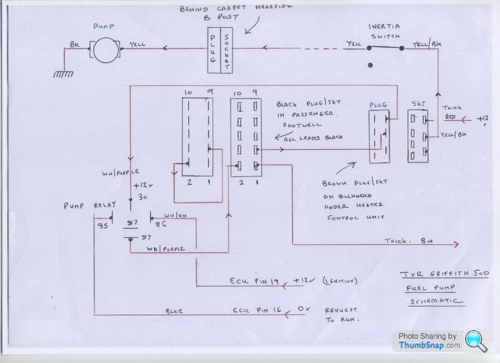
Taken from here - http://www.bertram-hill.com/fuel-pump-schematic.ht...
Visit the link as there is plenty of info
Taken from here - http://www.bertram-hill.com/fuel-pump-schematic.ht...
Visit the link as there is plenty of info

Thanks so much for this info. What I am going to do is start from the relay with a positive straight to the pin that should fire up the pump once ignition is on.
This in theory should prove that whole circuit is correct so I only need to then work out where the power comes to and from the relay. If that makes any sense as you say there could be a ECU fault here which is causing the problem. Maybe/maybe not. Time will tell thanks for the great info.
This in theory should prove that whole circuit is correct so I only need to then work out where the power comes to and from the relay. If that makes any sense as you say there could be a ECU fault here which is causing the problem. Maybe/maybe not. Time will tell thanks for the great info.
.. and to complete the story:
Ignition On
Main Relay and Fuel Pump Relay
With ignition On the ECU regularly measures the input Main Voltage level at pin 2, if it is 0 Vdc or drops below a certain level either as a result of a missing/faulty Main Relay or low battery voltage, an 'injectors have insufficient or no voltage supply' condition is flagged and the Fuel Pump is switched Off by the ECU, via the Fuel Pump relay.
How are the Fuel Pump and Main Voltage relays interlinked?
These relays are used in two different circuits and when ignition On is sensed separately controlled from ECU pin 16 and pin 12, respectively. If one of the relays is faulty then the respective +12 Vdc supplies are not realised, swapping relays simply means the Fuel Pump supplies are made and not Main Voltage, or vice versa.
A +12Vdc battery voltage (NG and N) is permanently applied to:
• Fuel Pump Relay (COM pin 30)
• Main Relay (COM pin 30 and Coil pin 86)
• ECU +ve supply (pin 15).
When ignition is switched On, the ECU, via pin 12, earths the Main Relay (Coil pin 85, Blue/Red), and the relay is energised feeding +12Vdc (two Brown/Orange) to:
• injector circuits
• AFM
• ECU pin 2, where Main Voltage is monitored for injection pulse width control purposes.
Also +12Vdc (White/Slate) is applied to:
• Fuel Pump Relay (Coil pin 86)
• ECU ignition sense (pin 19).
The ECU, via pin 16, now earths the Fuel Pump Relay (Coil pin 85, Blue/ Purple), the relay is energised feeding +12Vdc (White/Orange) to:
• Lambda sensors
• fuel pump (White/ Purple) via a fuse and Inertia Switch
• Purge Control Valve (if fitted).
Voltage states: there is a permanent +12 Vdc battery voltage to pin 30 of the Fuel Pump relay regardless of whether the Main Relay is in circuit, or not, so the Main Relay is not wired directly in series and does not supply power directly to the Fuel Pump relay; the ECU pin 16 earth control line to pin 85 of the Fuel Pump relay does depend on whether the Main Relay is in circuit, with the Main Relay in circuit the voltage level stays at about 0V (it does rise slightly) so as to prime the fuel rail until the delay counter times out and then it rises fully to +12Vdc to de-energise the coil if cranking doesn't occur, with the Main Relay completely removed pin 85 goes immediately to +12Vdc, keeping the Fuel Pump relay Off.
Conclusion: the ECU senses when the Main Relay is not in circuit and is responsible for controlling Fuel Pump On/Off, via pin 16, accordingly; therefore:
• A failed FP relay = no fuel.
• A failed Main relay = no main voltage sensing = no FP relay = no fuel.
• Swapping either failed relay = no fuel.
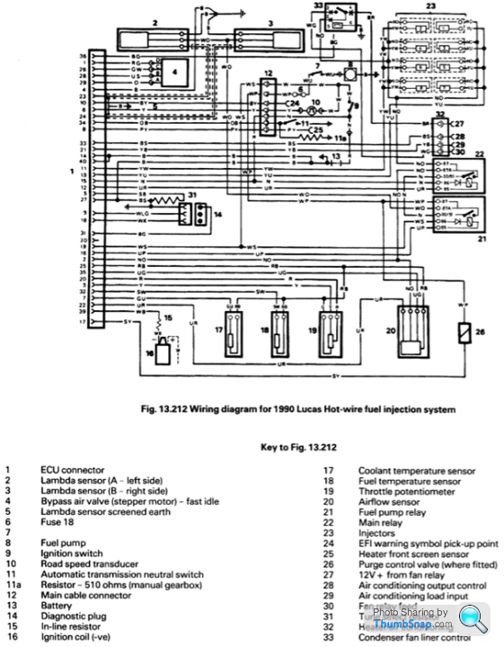
Note: The above relates to a '92 TVR Griffith, where the two relays are wired and colour coded in accordance with the Land Rover 14CUX schematic diagram - dated 1990. Later cars will more than likely have differences to cable colour coding, but the basic ECU/relay/fuel pump operation remains the same.
Ignition On
Main Relay and Fuel Pump Relay
With ignition On the ECU regularly measures the input Main Voltage level at pin 2, if it is 0 Vdc or drops below a certain level either as a result of a missing/faulty Main Relay or low battery voltage, an 'injectors have insufficient or no voltage supply' condition is flagged and the Fuel Pump is switched Off by the ECU, via the Fuel Pump relay.
How are the Fuel Pump and Main Voltage relays interlinked?
These relays are used in two different circuits and when ignition On is sensed separately controlled from ECU pin 16 and pin 12, respectively. If one of the relays is faulty then the respective +12 Vdc supplies are not realised, swapping relays simply means the Fuel Pump supplies are made and not Main Voltage, or vice versa.
A +12Vdc battery voltage (NG and N) is permanently applied to:
• Fuel Pump Relay (COM pin 30)
• Main Relay (COM pin 30 and Coil pin 86)
• ECU +ve supply (pin 15).
When ignition is switched On, the ECU, via pin 12, earths the Main Relay (Coil pin 85, Blue/Red), and the relay is energised feeding +12Vdc (two Brown/Orange) to:
• injector circuits
• AFM
• ECU pin 2, where Main Voltage is monitored for injection pulse width control purposes.
Also +12Vdc (White/Slate) is applied to:
• Fuel Pump Relay (Coil pin 86)
• ECU ignition sense (pin 19).
The ECU, via pin 16, now earths the Fuel Pump Relay (Coil pin 85, Blue/ Purple), the relay is energised feeding +12Vdc (White/Orange) to:
• Lambda sensors
• fuel pump (White/ Purple) via a fuse and Inertia Switch
• Purge Control Valve (if fitted).
Voltage states: there is a permanent +12 Vdc battery voltage to pin 30 of the Fuel Pump relay regardless of whether the Main Relay is in circuit, or not, so the Main Relay is not wired directly in series and does not supply power directly to the Fuel Pump relay; the ECU pin 16 earth control line to pin 85 of the Fuel Pump relay does depend on whether the Main Relay is in circuit, with the Main Relay in circuit the voltage level stays at about 0V (it does rise slightly) so as to prime the fuel rail until the delay counter times out and then it rises fully to +12Vdc to de-energise the coil if cranking doesn't occur, with the Main Relay completely removed pin 85 goes immediately to +12Vdc, keeping the Fuel Pump relay Off.
Conclusion: the ECU senses when the Main Relay is not in circuit and is responsible for controlling Fuel Pump On/Off, via pin 16, accordingly; therefore:
• A failed FP relay = no fuel.
• A failed Main relay = no main voltage sensing = no FP relay = no fuel.
• Swapping either failed relay = no fuel.
Note: The above relates to a '92 TVR Griffith, where the two relays are wired and colour coded in accordance with the Land Rover 14CUX schematic diagram - dated 1990. Later cars will more than likely have differences to cable colour coding, but the basic ECU/relay/fuel pump operation remains the same.
Edited by davep on Wednesday 7th June 13:51
Mike8448 said:
Thanks so much for this info. What I am going to do is start from the relay with a positive straight to the pin that should fire up the pump once ignition is on.
This in theory should prove that whole circuit is correct so I only need to then work out where the power comes to and from the relay. If that makes any sense as you say there could be a ECU fault here which is causing the problem. Maybe/maybe not. Time will tell thanks for the great info.
OK. I know that you know what you are doing but - If you are putting supplies to anything at the relay holder terminals don't mess up due to mirroring and all thatThis in theory should prove that whole circuit is correct so I only need to then work out where the power comes to and from the relay. If that makes any sense as you say there could be a ECU fault here which is causing the problem. Maybe/maybe not. Time will tell thanks for the great info.
I wouldn't put a direct supply to anything, you would be much safer using a 21 Watt bulb in a holder with some leads attached, you can then connect one end of the bulb to battery positive and the other to the fuel pump output terminal at the relay, the bulb should glow bright and then go out when you disconnect the pump at it terminals or close to it, this will prove all is good with the wiring. Should there be a short anywhere the bulb will glow brightly but not burn anything out, a 12 volt supply even when fused could cause more problems if there is a short somewhere
Whatever you do do, dont apply anything to the ECU to Fuel Pump relay control wire as you may damage the ECU
It's always dodgy applying power to wires when you are not sure if wires in the loom are good or shorted together - For instance, the ECU to fuel pump relay control wire could be shorting to another fuel pump wire or some other wire in the harness or through moisture/corrosion in the fuse-box, by applying a positive to 1 wire at the fuel pump relay could mean that due to a short somewhere you are in fact applying a positive to several wires/circuits
You can always play things the safe way by disconnecting the ECU and other componets before testing/applying a positive somewhere
As mentioned above, I know that you know what you are doing but mentioned a few good procedures just incase
Anyway going by that diagram you should be able to trace something through without stripping too much down
Yeah that is exactly what I have a bulb which 8s connected to the positive of the battery. Ecu is already removed. I didn't want to risk it. There should be no damp everything is dry stored for over 2 years now that I have had it. I'll update you all when I figure this out but the diagram is exactly what I needed
Far easier- just listen to the ECU relays - when you turn the ignition on (dont start) two relays should close with a click. Then after about 2- 3 seconds there should be a second click as the fuel pump relay drops out again as the engine is not running. This will prove you have 12v on the ECU and the relays are working. I dont know where the immobiliser is wired on the TVR, but it would make sense it was in the wiring to the pump, not between the ECU relays, so Id still expect them to click on power on (Im assuming here the ECU still gets power??) Maybe some one can try turning the ignition on with the immobiliser engaged and see if the relays click still?
Mike8448 said:
Yeah that is exactly what I have a bulb which 8s connected to the positive of the battery. Ecu is already removed. I didn't want to risk it. There should be no damp everything is dry stored for over 2 years now that I have had it. I'll update you all when I figure this out but the diagram is exactly what I needed
OK. Glad to be able to helpOk quick update. Me and the auto electrician have a spent a few hours going through all of this.
So first thing first.
My 12v supply relay is duff
My fuel relay is duff.
So we had two spare spare 4pin 30 87 relays then looped the 87 out to to the 5th pin. Technically doing the same thing.
So the 12v relay clicks on when ignition comes on. The fuel pump relay does not.
So my current thought is there maybe a Ecu issue.
The sigma immobiliser is also duff so I'm not sure whats happened. So we managed to pin out the immobiliser so it is no longer in use.
We then moved onto the coil to ensure there is power to the coil. Which we got.
However there was no spark. Anyway it turns out, I bought a new distributor unit which comes with a new amplifier. The new amplifier must be a different pin out as when we fitted the old one we have a spark.
So I can bypass the fuel pump relay and force fuel through the system. I have spark. I have 12v relay live.
But the engine won't cough into life. So I have a really good land rover spares place around the corner so I'm going to see if they have a spare 14cux ecu and see if that will turn on the fuel pump relay then I know mine is fooked.
I am pretty sure it is just simply then a case of swapping the eprom across. I hope.
Anyway I will update again soon once I have heard the engine bark 😂
Gassing Station | Griffith | Top of Page | What's New | My Stuff