Mobile Fuel Pump Mechanic
Discussion


PM me and I will send you a circuit diagram.
To get you going some simple tests.
If you don't do electrics think of it as water flowing through pipes. It flows from plus to minus.
Look at the diagram for the relays. When water flows 86 to 85 it allows water to flow 30 to both 87s.
Come back with your test results so we can mark your work and set your next homework.
Steve
To get you going some simple tests.
- First confirm you have found the right relays. to do this check this thread https://www.pistonheads.com/gassing/topic.asp?h=0&...
- Pull both relays and confirm that they have 5 pins marked....30, 85, 86, 87, 87. The 87 pins must not be 87a, 87b, 87c just plain 87.
- Clear the immobiliser and turn on the ignition. Test for volts at the fuel pump relay pin 86.
If you don't do electrics think of it as water flowing through pipes. It flows from plus to minus.
Look at the diagram for the relays. When water flows 86 to 85 it allows water to flow 30 to both 87s.
Come back with your test results so we can mark your work and set your next homework.
Steve
I think you are over complicating things, just buy a new pump! Worse case senario, you now have a spare

new fuel pump
Coefficient said:
My lack of electronics Knowledge is definitely a bit of a sticking point now. With the voltmeter I can see voltage and resistance between pins 85 and 86 on the ECU relay, hence the clock, but nothing between 30 and 87. So I would have expected no power to ECU but having read another thread, and hearing the stepper motor whirr, I would expect that there is power ??
Any idea what I’m doing wrong?
Cheers
Fuse 2 feeds pin 30 according to the diagram, fuse 12 and 13 come in to play also.Any idea what I’m doing wrong?
Cheers
Steve_D said:
phillpot said:
I think you are over complicating things, just buy a new pump! Worse case senario, you now have a spare
You seem to have missed the bit where he has tested the pump and it is working but does not have a live feed on the wires to the pump.Steve


This ^ or you can ground the FP - pin on the relay holder/base that comes from the ECU to keep the relay energised  but this is best left to someone who under stands electrics, far more meaningful results can be had with a test light or bulb than a multi-meter with this kind of stuff because at least your loading the circuit
but this is best left to someone who under stands electrics, far more meaningful results can be had with a test light or bulb than a multi-meter with this kind of stuff because at least your loading the circuit You mentioned RoverGauge would not display anything when plugged in ? Very suspicious, it possibly means the ECU has no power or is immobilised still. If the ECU is getting power, the the main relay and fp relay close together with ignition on with a click. A few seconds later the Fp relay will drop out with another a click if the ECU has initialised.
Not sure what was happening yesterday but thanks to everyone for the tips. After checking fuse 2 and using the mutimeter correctly (to negative terminal) I determined that the ECU was in fact powered and the stepper motor indicated it was working. So I persevered with Rovergauge and bingo:
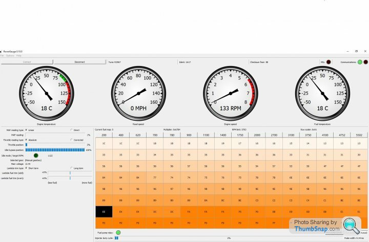
So now I can see that the fuel pump is manually activated in ECU (thanks Mark) but the voltmeter still says no volts between FP 86 and the negative terminal (easiest to find in the footwell than a good earth). So the FP relay is not clicking, instead there is something behind the dash that is clicking, plus the ECU relay.
Fuses 12 and 13 checked but seem to be OK. Voltmeter shows good 12.7V between FP relay pin 30 and neg terminal.
Any marks on my homework so far?
Cheers,
James
Sorry, yes, the main ECU relay is fully powered. I wasn’t measuring it properly before, ie. not to the negative terminal or a good earth. RGauge shows ECU is working normally. I’m not sure why it didn’t work before but disconnecting and reconnecting at the 3 pin junction seemed to sort it.
Coefficient said:
So the FP relay is not clicking, instead there is something behind the dash that is clicking, plus the ECU relay.
Fuses 12 and 13 checked but seem to be OK. Voltmeter shows good 12.7V between FP relay pin 30 and neg terminal.
Any marks on my homework so far?
Cheers,
James
I can see where Steve is going with this- but can you get the FP relay to click on /off with RoverGauge? You dont need the coil pulse to do this. Also the FP relay has two 12v outputs that get activated at the same time- one goes to the fuel pump, and the other goes to the heaters on the two lambda probes- so its worth popping your test meter on the heater to ground and see whats on there. The loom wire is orange /white, and the heater to the probe is red. There lambda cables are extended on the TVR and you will find a socket buried down with the loom on top of the v8 , or the ones strapped to the chassis at the front near the probes. Just to check- you have not changed the FP relay out at any time and swapped it with another relay? Its just the pin configuration on these relays is NOT the same as your bog standard 2 way car relay. The fact you have a click form the dashboard worries me as this is where your immobiliser will be and this is where your troubles started. How did you bypass the immobiliser?Fuses 12 and 13 checked but seem to be OK. Voltmeter shows good 12.7V between FP relay pin 30 and neg terminal.
Any marks on my homework so far?
Cheers,
James
The immobiliser is not bypassed at the moment, it has been replaced with a new MT2(?), which is connected to ECU and starter, both of which are working.
The FP relay is definitely not clicking when I cycle the manual override.
I had a look at the lambda anyway. Two leads were around 200mV one was 0 ish. I think it was blue. Does that make sense? Pretty sure it was a lambda lead since I changed a probe before the last layup.
The original relays were connected when problem started. First thing I did was order two new relays of correct type from TVR parts. The ECU relay is clearly working, so i swapped them over as a sanity check. The ECU still worked, the FP did not. I think I’ll swap fuses 12 and 13 next, even though they look good to my untrained eye.
One other thing I should mention. When the problem started, the first couple of times, it just went away when I pulled out the footwell cabling to take a look. If I wanted to run a fly lead from the ignition circuit, to pin 86 on the relay, as a check, then how would I do that? Or should I just run it straight to the positive terminal? I guess lack of fuse could be an issue?
The main relay and fuel pump relay coils are supplied differently-
The main relay gets its 12v coil feed feed from the brown wire- this is 12v from the battery on pin 86. The relay is activated by a control wire blue/red that gets grounded by the ECU on pin 85
The fuel pump relay coil is fed with 12v from the ignition switch via a white /grey wire on pin 86. The ECU grounds pin 85 by a blue purple wire to activate the coil and close the relay. If the ECU is faulty or a break in the connection to it, you will see 12v on the blue purple wire all the time. It should be near 0 volts if you turn the fuel pump on with RoverGauge.
Now my disclaimer! This is from a Range Rover manual, just incase the TVR is different, but far as I know this bit of the loom is as Lucas built it.
Steve_D said:
Right next homework.
If there are no volts at fuel pump relay P86 (ign. on and immobiliser disarmed) go to the positive terminal of the coil and see if you have volts there.
Steve
Not seen your answer on this yet.If there are no volts at fuel pump relay P86 (ign. on and immobiliser disarmed) go to the positive terminal of the coil and see if you have volts there.
Steve
The fact you have no volts on fuel pump relay pin 86 is the root of the problem.
This should be supplied from fuse 2 via the immobiliser. This fuse also supplies the ignition coil and ECU pin 19 which is why I asked for you to check for volts at the coil.
This is now doubly important as all these connections are joined at a blue device in the footwell loom called a 'loopback Connector' which is basically a way of joining a number of wires together. The fact that you now say things change when you move the loom points to this connector as the possible culprit.
You could also set rovergauge to run the pump continuous then start moving the wires around the loopback connector and see if you can get things back to life.
Steve
Edited by Steve_D on Wednesday 1st July 08:49
Steve_D said:
This fuse also supplies the ignition coil and ECU pin 19 which is why I asked for you to check for volts at the coil.
This is now doubly important as all these connections are joined at a blue device in the footwell loom called a 'loopback Connector' which is basically a way of joining a number of wires together. The fact that you now say things change when you move the loom points to this connector as the possible culprit.
You could also set rovergauge to run the pump continuous then start moving the wires around the loopback connector and see if you can get things back to life.
Steve
Ah- I thought your where going to check for 12v on the coil to make sure we have the coil trigger back to the ECU to trigger the pump. Never assume anything.... This is now doubly important as all these connections are joined at a blue device in the footwell loom called a 'loopback Connector' which is basically a way of joining a number of wires together. The fact that you now say things change when you move the loom points to this connector as the possible culprit.
You could also set rovergauge to run the pump continuous then start moving the wires around the loopback connector and see if you can get things back to life.
Steve
Edited by Steve_D on Wednesday 1st July 08:49

OK. Just double checked. Still sub 1V at pin 85 & 86 and checked that still 12V+ at pin 30. Steve, I think from your diagram and your description that you mean fuse 12, so I changed this out for a new one just in case. Still no fuel pump. Out of curiosity I also removed the ignition switch relay but that just meant that the ignition systems never came on. So yes, I’m thinking the loop back thingumy. What next?
Just seen reread comments about ignition coil. I’ve not checked the voltage but the starter motor turns over, won’t this be the same supply?
Just seen reread comments about ignition coil. I’ve not checked the voltage but the starter motor turns over, won’t this be the same supply?
Edited by Coefficient on Wednesday 1st July 13:44
Edited by Coefficient on Wednesday 1st July 13:53
Coefficient said:
OK. Just double checked. Still sub 1V at pin 85 & 86 and checked that still 12V+ at pin 30. Steve, I think from your diagram and your description that you mean fuse 12, so I changed this out for a new one just in case. Still no fuel pump. Out of curiosity I also removed the ignition switch relay but that just meant that the ignition systems never came on. So yes, I’m thinking the loop back thingumy. What next?
Just seen reread comments about ignition coil. I’ve not checked the voltage but the starter motor turns over, won’t this be the same supply?
Starter is a different circuit.Just seen reread comments about ignition coil. I’ve not checked the voltage but the starter motor turns over, won’t this be the same supply?
My bad...yes fuse12.
So next either test for volts at the coil or locate the loopback connector.
You don't have to disconnect the loopback connector you can just use your meter into the back of it. In a line there should be 3 white/green wires and one black wire. Test all of these. Before you go testing it set rovergauge to run the fuel pump because as you start twisting the connector about to get your probe in you may hear the pump & relay if there is a bad connection in there.
Best of luck........ getting close.
Steve
Gassing Station | Griffith | Top of Page | What's New | My Stuff