
Clutch alignment tool
Discussion


You mentioned that you have a 3d printer,
- the T5 spline is 1" diameter, 23 tooth pattern, and a 15mm spigot bearing diameter. This is standard for the AJP Speed 6 and V8 engined cars with the T5 gearbox.
ChatGPT says:
Recommended design
For FDM printing, I'd make the tool in three sections:
Section Diameter Length
Handle 35 40 mm 70 mm
Clutch alignment section 24.8 25.0 mm 40 50 mm
Pilot bearing section 14.90 mm 20 25 mm
I'd add:
a 1 mm chamfer on the pilot end
generous fillets between sections
a slight taper (about 0.1 mm) on the alignment section so it slides into the clutch disc easily.
Why not model the 23 splines?
For clutch installation, it's unnecessary. The purpose is simply to center the clutch disc while tightening the pressure plate.
A smooth 24.9 25.0 mm section centers the disc extremely well because it locates on the root diameter of the spline. In fact, many commercial plastic alignment tools are smooth rather than fully splined.
Advantages:
prints on any FDM printer
stronger than a fine spline print
no support required
won't jam in the clutch disc
Material
I'd print it in:
PETG (my first choice)
ABS
Nylon
PLA would probably work for occasional use, but PETG is tougher and less likely to deform if left in a hot garage.
If you want a fully splined version
I can also generate an accurate 23-tooth involute spline model. It'll fit more like the gearbox input shaft, but I'd recommend printing it on a resin printer or a very well-tuned FDM printer with a 0.2 mm nozzle for the best results.
I can generate the files
I can produce:
? STL ready to print
? STEP file for machining or editing
? Fusion 360 model
? OpenSCAD source
I can also include a "TVR AJP 23T × 15 mm" label embossed into the handle so it won't get mixed up with other alignment tools in your toolbox.
- the T5 spline is 1" diameter, 23 tooth pattern, and a 15mm spigot bearing diameter. This is standard for the AJP Speed 6 and V8 engined cars with the T5 gearbox.
ChatGPT says:
Recommended design
For FDM printing, I'd make the tool in three sections:
Section Diameter Length
Handle 35 40 mm 70 mm
Clutch alignment section 24.8 25.0 mm 40 50 mm
Pilot bearing section 14.90 mm 20 25 mm
I'd add:
a 1 mm chamfer on the pilot end
generous fillets between sections
a slight taper (about 0.1 mm) on the alignment section so it slides into the clutch disc easily.
Why not model the 23 splines?
For clutch installation, it's unnecessary. The purpose is simply to center the clutch disc while tightening the pressure plate.
A smooth 24.9 25.0 mm section centers the disc extremely well because it locates on the root diameter of the spline. In fact, many commercial plastic alignment tools are smooth rather than fully splined.
Advantages:
prints on any FDM printer
stronger than a fine spline print
no support required
won't jam in the clutch disc
Material
I'd print it in:
PETG (my first choice)
ABS
Nylon
PLA would probably work for occasional use, but PETG is tougher and less likely to deform if left in a hot garage.
If you want a fully splined version
I can also generate an accurate 23-tooth involute spline model. It'll fit more like the gearbox input shaft, but I'd recommend printing it on a resin printer or a very well-tuned FDM printer with a 0.2 mm nozzle for the best results.
I can generate the files
I can produce:
? STL ready to print
? STEP file for machining or editing
? Fusion 360 model
? OpenSCAD source
I can also include a "TVR AJP 23T × 15 mm" label embossed into the handle so it won't get mixed up with other alignment tools in your toolbox.
On the twin plate clutch, it is important for alignment, but more so, I would say that a good tool it is needed to set the pedal height, as with my original steel (a cropped off input shaft) I could not see the shaft spin and did not have a ring to spin it, as to gauge the drag/release of the plates, (with the second person in the car pressing the pedal) as it was dark under the car. I have to thank BB from the other thread for gifting me this one.
For the un-knowing the cover/plates are added to a stepped fly wheel (2.5mm for those machining the face, the step needs machining too), then aligned at that point, the bell-housing added, with the release bearing/slave fitted into the bell housing and the pedal set up, THEN the gearbox is offered up to the car. A@
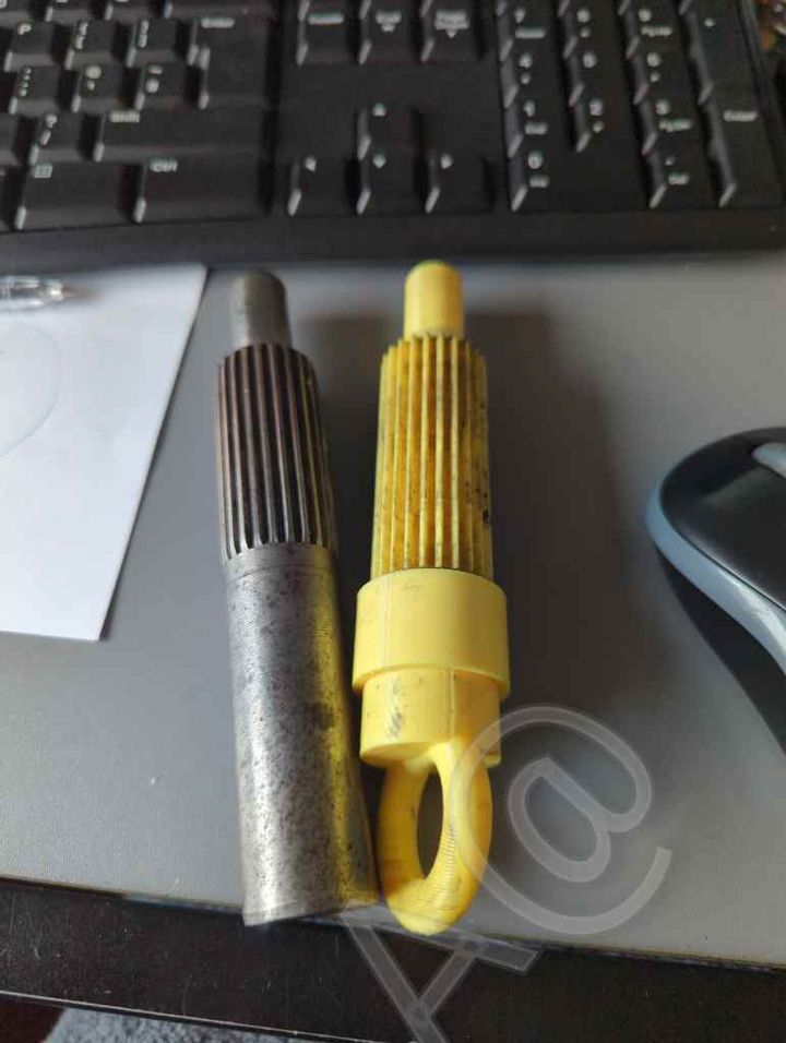
For the un-knowing the cover/plates are added to a stepped fly wheel (2.5mm for those machining the face, the step needs machining too), then aligned at that point, the bell-housing added, with the release bearing/slave fitted into the bell housing and the pedal set up, THEN the gearbox is offered up to the car. A@
Edited by Adrian@ on Monday 27th July 13:14
Adrian@ said:
On the twin plate clutch, it is important for alignment, but more so, I would say that a good tool it is needed to set the pedal height, as with my original steel (a cropped off input shaft) I could not see the shaft spin and did not have a ring to spin it, as to gauge the drag/release of the plates, (with the second person in the car pressing the pedal) as it was dark under the car. I have to thank BB from the other thread for gifting me this one.
For the un-knowing the cover/plates are added to a stepped fly wheel (2.5mm for those machining the face, the step needs machining too), then aligned at that point, the bell-housing added, with the release bearing/slave fitted into the bell housing and the pedal set up, THEN the gearbox is offered up to the car. A@
I have the Bellhousing in place already. Will I have to take it off again to align the clutch plates?For the un-knowing the cover/plates are added to a stepped fly wheel (2.5mm for those machining the face, the step needs machining too), then aligned at that point, the bell-housing added, with the release bearing/slave fitted into the bell housing and the pedal set up, THEN the gearbox is offered up to the car. A@
Edited by Adrian@ on Monday 27th July 13:14
milothepeanut said:
I have the Bellhousing in place already. Will I have to take it off again to align the clutch plates?
The basic alignment what you see in any clutch process (you see the extensions with tape and Halfords etc. kits) BUT the twin clutch is deep through the slave.Assuming you have done the basics you have done everything correctly.
You then need to do the next step of having a splined tool to have a second person press the clutch pedal several times to work out a happy bite point and adjust the clevis pin rod to ensure the clutch does not over centre in use (if you are running the same cover/cage it will be near, I changed actual cage heights and had refaced flywheel so this matters).
The tool allows you to asses the bite point (spinning the tool as the pedal is pressed will tell you it is free), whilst stopping the two plates floating/dropping off centre as the 2nd person presses the pedal. Once the pedal is sorted you pull the tool and offer up the gearbox. A@
BTW Gordon's T bar pictures pretty much show you as it is.
Edited by Adrian@ on Monday 27th July 15:30
jstx said:
You mentioned that you have a 3d printer,
- the T5 spline is 1" diameter, 23 tooth pattern, and a 15mm spigot bearing diameter. This is standard for the AJP Speed 6 and V8 engined cars with the T5 gearbox.
ChatGPT says:
Recommended design
For FDM printing, I'd make the tool in three sections:
Section Diameter Length
Handle 35 40 mm 70 mm
Clutch alignment section 24.8 25.0 mm 40 50 mm
Pilot bearing section 14.90 mm 20 25 mm
I'd add:
a 1 mm chamfer on the pilot end
generous fillets between sections
a slight taper (about 0.1 mm) on the alignment section so it slides into the clutch disc easily.
Why not model the 23 splines?
For clutch installation, it's unnecessary. The purpose is simply to center the clutch disc while tightening the pressure plate.
A smooth 24.9 25.0 mm section centers the disc extremely well because it locates on the root diameter of the spline. In fact, many commercial plastic alignment tools are smooth rather than fully splined.
Advantages:
prints on any FDM printer
stronger than a fine spline print
no support required
won't jam in the clutch disc
Material
I'd print it in:
PETG (my first choice)
ABS
Nylon
PLA would probably work for occasional use, but PETG is tougher and less likely to deform if left in a hot garage.
If you want a fully splined version
I can also generate an accurate 23-tooth involute spline model. It'll fit more like the gearbox input shaft, but I'd recommend printing it on a resin printer or a very well-tuned FDM printer with a 0.2 mm nozzle for the best results.
I can generate the files
I can produce:
? STL ready to print
? STEP file for machining or editing
? Fusion 360 model
? OpenSCAD source
I can also include a "TVR AJP 23T × 15 mm" label embossed into the handle so it won't get mixed up with other alignment tools in your toolbox.
Alternatively you can start with an existing Porsche 3d model, which has the same spline size and count, and stretch the splined area as required.- the T5 spline is 1" diameter, 23 tooth pattern, and a 15mm spigot bearing diameter. This is standard for the AJP Speed 6 and V8 engined cars with the T5 gearbox.
ChatGPT says:
Recommended design
For FDM printing, I'd make the tool in three sections:
Section Diameter Length
Handle 35 40 mm 70 mm
Clutch alignment section 24.8 25.0 mm 40 50 mm
Pilot bearing section 14.90 mm 20 25 mm
I'd add:
a 1 mm chamfer on the pilot end
generous fillets between sections
a slight taper (about 0.1 mm) on the alignment section so it slides into the clutch disc easily.
Why not model the 23 splines?
For clutch installation, it's unnecessary. The purpose is simply to center the clutch disc while tightening the pressure plate.
A smooth 24.9 25.0 mm section centers the disc extremely well because it locates on the root diameter of the spline. In fact, many commercial plastic alignment tools are smooth rather than fully splined.
Advantages:
prints on any FDM printer
stronger than a fine spline print
no support required
won't jam in the clutch disc
Material
I'd print it in:
PETG (my first choice)
ABS
Nylon
PLA would probably work for occasional use, but PETG is tougher and less likely to deform if left in a hot garage.
If you want a fully splined version
I can also generate an accurate 23-tooth involute spline model. It'll fit more like the gearbox input shaft, but I'd recommend printing it on a resin printer or a very well-tuned FDM printer with a 0.2 mm nozzle for the best results.
I can generate the files
I can produce:
? STL ready to print
? STEP file for machining or editing
? Fusion 360 model
? OpenSCAD source
I can also include a "TVR AJP 23T × 15 mm" label embossed into the handle so it won't get mixed up with other alignment tools in your toolbox.
ukkid35 said:
Are you fitting the gearbox before installing the engine
Or are you fitting the gearbox with the engine in situ?
I have lots of experience with the latter, none with the former
But I have a spare damaged input shaft which is a perfect alignment tool which you can borrow if needed
A borrow would be great. I am near Colchester. Are you in this part of the country?Or are you fitting the gearbox with the engine in situ?
I have lots of experience with the latter, none with the former
But I have a spare damaged input shaft which is a perfect alignment tool which you can borrow if needed
Forums | Cerbera | Top of Page | What's New | My Stuff