Discussion


Hi all,
Helping @mattgreenworks by looking at the various ECU's. Posting some findings to this thread to maybe help future restorers.
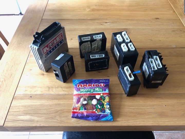
He kindly included some sweets.
First module to look at is the ignition ecu
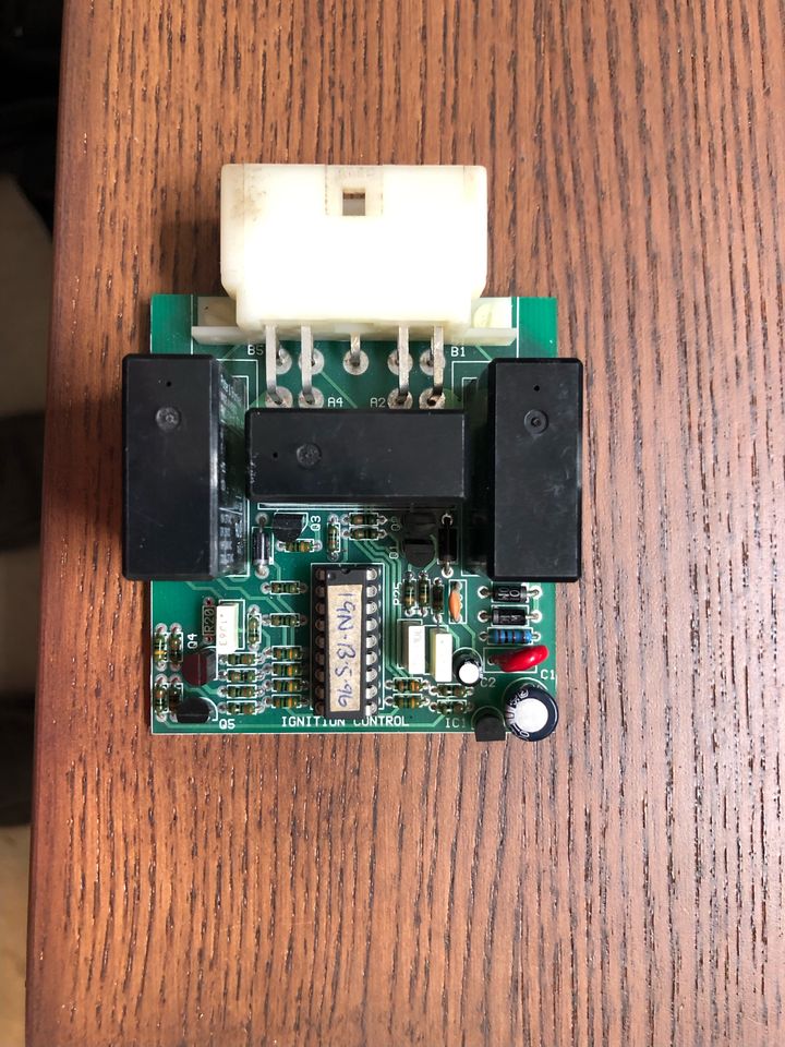
It doesn't look too bad from this side. Interesting to note the hand written label on the PIC16. I wonder if this chip can be read?
The underside of the board looks a little mucky and someone has been there with a soldering iron
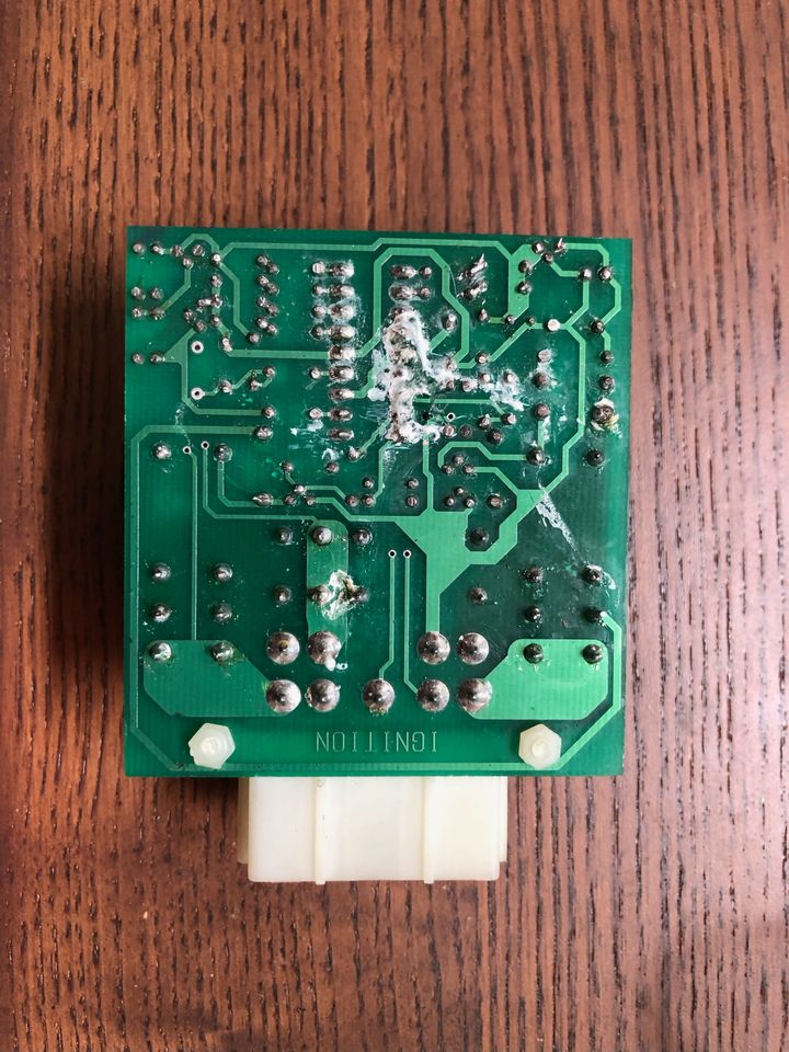
The board seems to function correctly, but I've not tried to load the outputs.
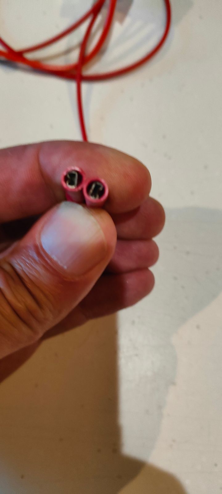
A question to the community: what size are the terminals and is it possible to by slide on connectors for testing purposes?
I'm quite tempted to reverse engineer this board and produce a schematic - unless there is one already?
Cheers
Mark
Helping @mattgreenworks by looking at the various ECU's. Posting some findings to this thread to maybe help future restorers.
He kindly included some sweets.
First module to look at is the ignition ecu
It doesn't look too bad from this side. Interesting to note the hand written label on the PIC16. I wonder if this chip can be read?
The underside of the board looks a little mucky and someone has been there with a soldering iron
The board seems to function correctly, but I've not tried to load the outputs.
A question to the community: what size are the terminals and is it possible to by slide on connectors for testing purposes?
I'm quite tempted to reverse engineer this board and produce a schematic - unless there is one already?
Cheers
Mark
Hi Mark and welcome to the TVR Cerbera control box club 
I test(ed) all of my boxes with a 240V -> 12V arcade PSU and the terminal connections for applying the power can be connected using mini female crimp connectors as the picture below shows
If you need any hand with these boxes or their functions etc. just shout - between Imran and I, I think we have pulled all of them apart at some point and spent time getting them working again
For the PIC, unluckily no they are encrypted so can't be read with an EPROM reader - I tried and you just get unusable stuff - Paul who repairs these has the original source code but can't share it due to an NDA or similar with TVR
HTH
Test PSU
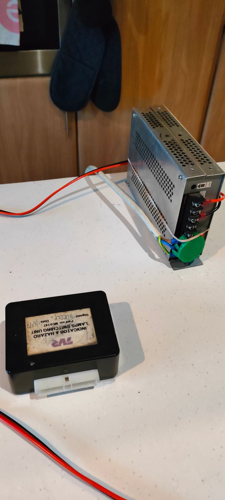
Power and negative connectors
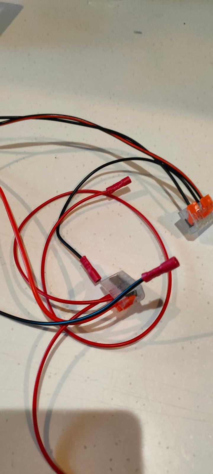
Mini female blade connectors - I use shielded ones as the pins are quite close together on the control boxes and widen the connector a little bit with a mini screwdriver blade
I test(ed) all of my boxes with a 240V -> 12V arcade PSU and the terminal connections for applying the power can be connected using mini female crimp connectors as the picture below shows
If you need any hand with these boxes or their functions etc. just shout - between Imran and I, I think we have pulled all of them apart at some point and spent time getting them working again
For the PIC, unluckily no they are encrypted so can't be read with an EPROM reader - I tried and you just get unusable stuff - Paul who repairs these has the original source code but can't share it due to an NDA or similar with TVR
HTH
Test PSU
Power and negative connectors
Mini female blade connectors - I use shielded ones as the pins are quite close together on the control boxes and widen the connector a little bit with a mini screwdriver blade
Hi,
I've ordered some connectors. In the meantime I've been using logic probe clips.
I have a reasonable setup here with a bench power supply (wish I'd bought a 2 channel version), multi-meter and a 4 channel scope - I was once an electronics engineer.
Today I setup a better test for the ignition ecu. The start relay wasn't triggering, which is what Matt had seen when it was in the car. Fortunately, the relay itself is fine as is the PIC output driving the transistor to energise the relay. The transistor (Q3) is not working. They are still available, so I've ordered some.
I've started to draw a schematic, though I'm not sure it's going to me much use.
Mark
I've made a start on the schematic. Not added the 5v regulator parts, all of resistor values or designators
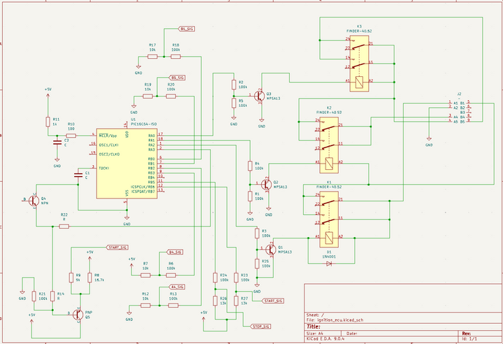
Interesting to see that relay 2 outputs to A4 the voltage that's from relay 3 (starter) but isn't connected to the harness.
There's a couple of other interesting things going on: The outputs are fedback to the PIC - does the firmware do anything with this data? The start signal is effectively duplicated.
Mark
While I'm here. I think I've now capture all the components and connections. The resistor designators are actually under the resistors, making it impossible to read.
I've noticed in photos of other units that R4 & R8 (R6 & R7 in my drawing) are not fitted. This signal is monitoring the output on a non connected pin. I wonder what plans they had for the board?
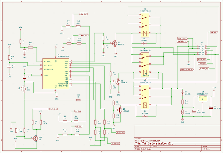
I've noticed in photos of other units that R4 & R8 (R6 & R7 in my drawing) are not fitted. This signal is monitoring the output on a non connected pin. I wonder what plans they had for the board?
Markb139 said:
While I'm here. I think I've now capture all the components and connections.
Great progress 
While I'm here, and not sure if you know the behaviour of the PIC but this is how it works.
B2 - Start Signal
1st momentary touch to GND = B1 -> +12V = Ignition Drive
2nd touch and hold to GND = B5 -> +12V = Starter Drive and B1 stays at +12V (ignition)
Disconnect from GND = B5 -> N/C (starter) and B1 stays at +12V (ignition)
You can achieve the same as the 1st two steps above by holding to GND straight away and the PIC will do B1 -> +12V, wait a second or so and then do B5 -> 12V until you disconnect it., then it follows the 3rd step above
B3 - Stop Signal
Touch or hold to GND = B1 -> N/C (kills ignition)
I also noticed that A4 is a spare drive so maybe they had plans for a remote start or similar? (*nobody will probably ever know I guess)
Forum | Cerbera | Top of Page | What's New | My Stuff