Steering wheel functions module circuit diagram
Discussion


Hi clever folk, has anyone reverse engineered the steering functions module please.
The R4 resister has let out the magic smoke, trying find out its value. I may have inadvertently pushed the ribbon cable in reverse 😢
If not a photo may help to see the colours. A circuit diagram would be brilliant. TIA.
The R4 resister has let out the magic smoke, trying find out its value. I may have inadvertently pushed the ribbon cable in reverse 😢
If not a photo may help to see the colours. A circuit diagram would be brilliant. TIA.
CER927 said:
Hi clever folk, has anyone reverse engineered the steering functions module please.
The R4 resister has let out the magic smoke, trying find out its value. I may have inadvertently pushed the ribbon cable in reverse ?
If not a photo may help to see the colours. A circuit diagram would be brilliant. TIA.
No circuit diagram unluckily but I do have lots of photos and a spare unit The R4 resister has let out the magic smoke, trying find out its value. I may have inadvertently pushed the ribbon cable in reverse ?
If not a photo may help to see the colours. A circuit diagram would be brilliant. TIA.

Measuring the resistance across R4 is appears to be 10.2 Ohm and the colours as far as I can see are Brown, Black, Black, Gold which matches what a 10 Ohm resistor should be
Any more photos or measurements you need just let me know

Juddder
Thank you Judder, I (we) have had the steering wheel/column out this morning. I discovered that one of the hazard warning switch wires had been pulled out of its connector . A quick solder by a more competent friend, and then gently returned back into the car and hey presto, hazard warning lights are now working again. I also have indicators, horn, dim dip, washers and wipers working. So I am at a loss, as to what the burnt resistor does. Perhaps it is not completely kaput?
Pleasure and great that you have it all working again.
Often resistors are just used to stabilise bits of circuit so it might not be a critical component to getting the unit running (no schematic, just a logical guess )
If you meter across the resistor with a multi-meter on ohms setting you can see if the resistance is infinite (blown) or around 10 Ohms (still working) which will give you the heads up as to whether it is completely kaput or just wounded from (at a guess) have excess current going through it due to being grounded or similar
Often resistors are just used to stabilise bits of circuit so it might not be a critical component to getting the unit running (no schematic, just a logical guess
)If you meter across the resistor with a multi-meter on ohms setting you can see if the resistance is infinite (blown) or around 10 Ohms (still working) which will give you the heads up as to whether it is completely kaput or just wounded from (at a guess) have excess current going through it due to being grounded or similar
Seeing as I had the spare Steering Wheel Control Box out, I photographed and measured all of the other resistors so we all have it for reference
R1 - 100 K Ohm = Brown, Black, Black, Orange, Brown
R2 - 7 K Ohm = ?, ?, Black, Gold, Gold (Couldn't match the colours on this one but the values metered consistently at 7 K Ohm)
R3 - 1.2 K Ohm = Brown, Red, Black, Brown, Brown
R4 - 10 Ohm = Brown, Black, Black, Gold
R5 - N/C
R6 - 10 K Ohm = Brown, Black, Black, Red, Brown
R7 - 100 K Ohm = Brown, Black, Black, Orange, Brown
R8 - 100 K Ohm = Brown, Black, Black, Orange, Brown
R9 - 1.2 K Ohm = Brown, Red, Black, Brown, Brown
C2 - 1J63 - 1 uF, 5%, 63V plastic film capacitor
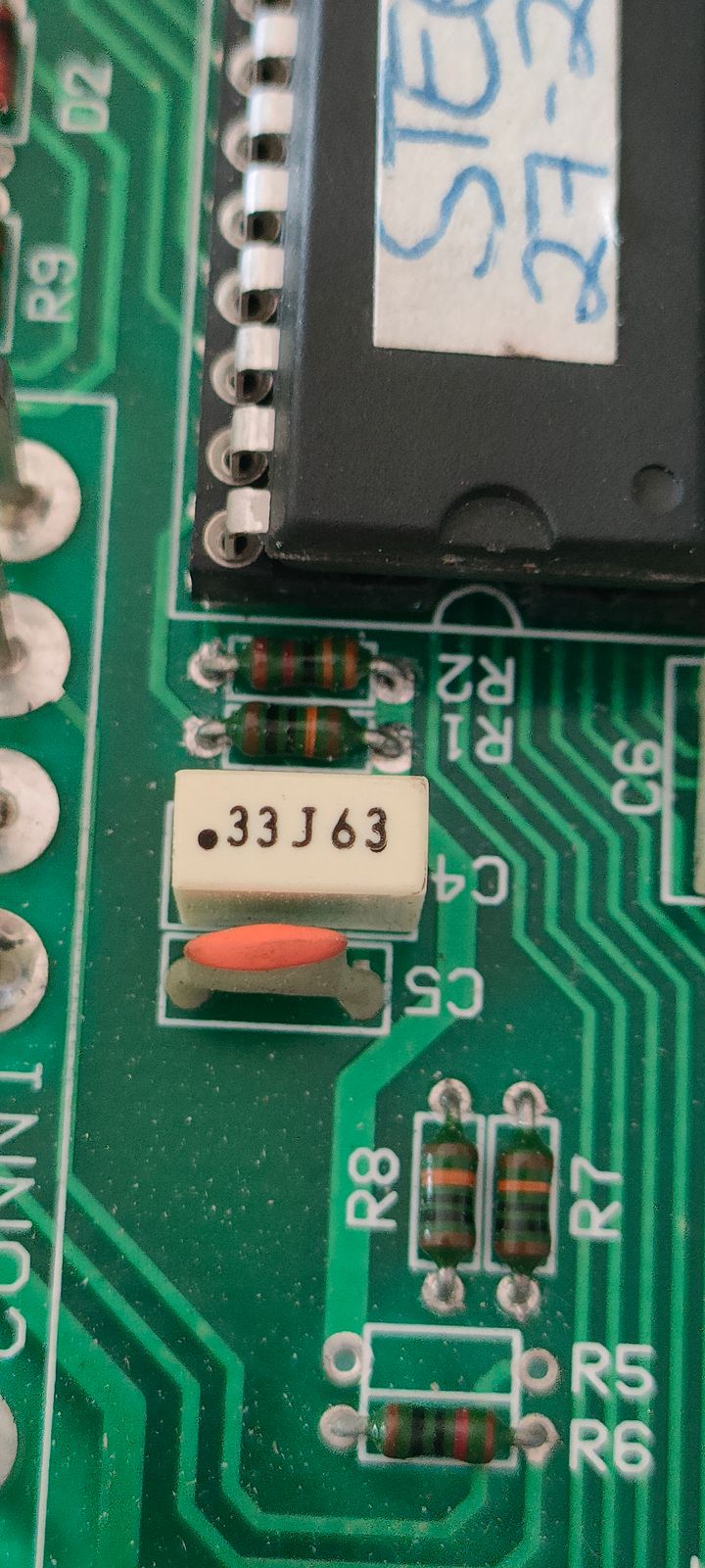
C4 - 33J63 - KEMET R82 Polyester Film Capacitor, 40 V ac, 63 V dc, ±5%, 330nF, Through Hole
C5 -
C6 - 10nJ100 - AV 100V 103 0.01UF 10NF 10nJ100 103J 5% R82 Correction capacitor
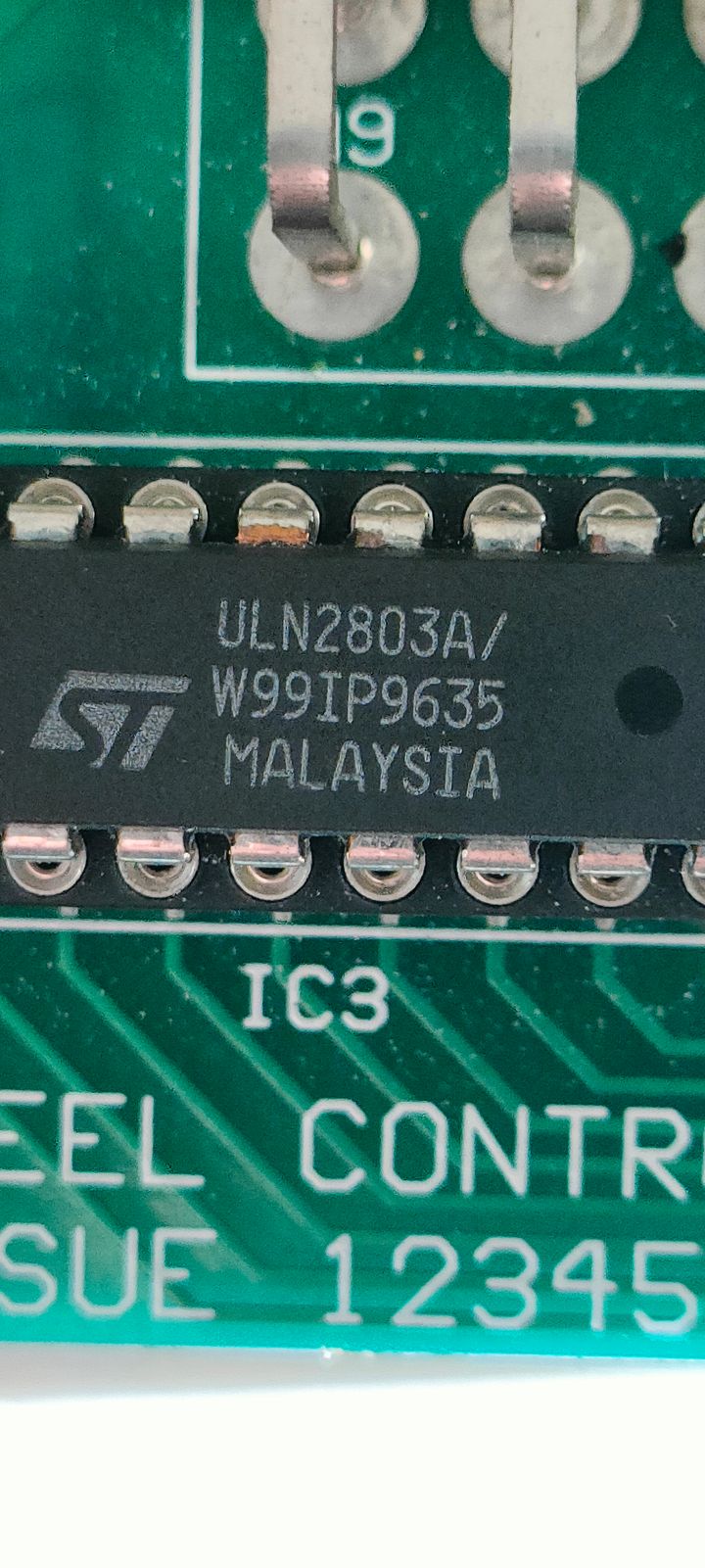
IC3 - ST Microelectronics ULN2803A - Eight Darlington Arrays
RESNET1 - Bi L81S 103 536
RESNET2 - Bi B99-3-R 220K - Dual-In-Line 220K Resistor Networks
R1 - 100 K Ohm = Brown, Black, Black, Orange, Brown
R2 - 7 K Ohm = ?, ?, Black, Gold, Gold (Couldn't match the colours on this one but the values metered consistently at 7 K Ohm)
R3 - 1.2 K Ohm = Brown, Red, Black, Brown, Brown
R4 - 10 Ohm = Brown, Black, Black, Gold
R5 - N/C
R6 - 10 K Ohm = Brown, Black, Black, Red, Brown
R7 - 100 K Ohm = Brown, Black, Black, Orange, Brown
R8 - 100 K Ohm = Brown, Black, Black, Orange, Brown
R9 - 1.2 K Ohm = Brown, Red, Black, Brown, Brown
C2 - 1J63 - 1 uF, 5%, 63V plastic film capacitor
C4 - 33J63 - KEMET R82 Polyester Film Capacitor, 40 V ac, 63 V dc, ±5%, 330nF, Through Hole
C5 -
C6 - 10nJ100 - AV 100V 103 0.01UF 10NF 10nJ100 103J 5% R82 Correction capacitor
IC3 - ST Microelectronics ULN2803A - Eight Darlington Arrays
RESNET1 - Bi L81S 103 536
RESNET2 - Bi B99-3-R 220K - Dual-In-Line 220K Resistor Networks
Edited by Juddder on Saturday 13th September 19:12
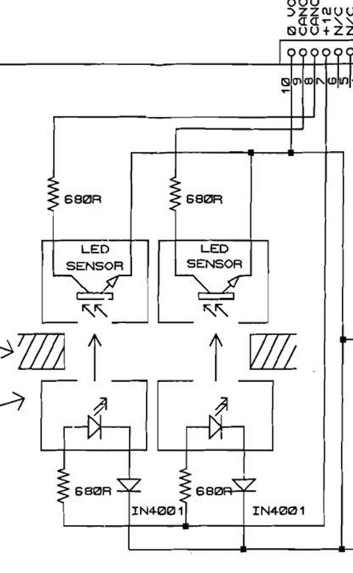
R4 is connected to pin 7 on the main 10 pin ribbon cable output, and that is +12V output, so I guess that justifies the thicker track
For CER927 if something shorted in his steering wheel column, and the +12V went to ground, I'm guessing that would take out R4 with the higher current flowing straight through the resistor
The +12V in the Steering Column is used to power the Optical Sensors that are used to cancel the turn signal, so if the indicators were the problem, which they are here, it could have caused the above
I spent sometime documenting my one of these when it blew, so here's as far as I got with the pinout which will hopefully help your KCad reverse engineering (*which is great to see BTW)
Alex
Steering Wheel Functions Control Unit

A1 - N/C
A2 - HEADLAMP SIGNAL (A1)
A3 - N/C
A4 - N/C
A5 -
A6 - WIPER 2 SIGNAL (A6)
A7 - MAIN BEAM SIGNAL (A0)
A8 - DIP BEAM SIGNAL (D13)
A9 - TURN LEFT SIGNAL (D10)

B1 - IGNITION
B2 - HORN DRIVE (A2)
B3 - HAZARD DRIVE (A3)
B4 - BATTERY
B5 - GND
B6 - WIPER 1 SIGNAL (A7)
B7 - N/C
B8 - WASHER SIGNAL (D12)
B9 - TURN RIGHT SIGNAL (D10)

10 Pin Ribbon (labelled right to left when looking at the back of the unit, pins in front of you)

10 - GND
9 - CANCEL RHT IP (D9)
8 - CANCEL LEFT IP (D8)
7 - +12V
6 - N/C
5 - N/C
4 - HORN INPUT (D7)
3 - DIP INPUT (D6)
2 - WASHER INPUT (D5)
1 - WIPER INPUT (D4)

5 Pin Ribbon

5 - N/C
4 - HAZARD W/L (D3)
3 - HAZARD SWITCH (D2)
2 - INDICATOR RIGHT (D0)
1 - INDICATOR LEFT (D1) Silver pins up RHS
Edited by Juddder on Wednesday 17th September 08:55
NZ fan said:
Hi all, just trying to identify what capacitor used to be here? ( 1997 4.2 Cerbera) I have asked Judder but was unable to send a picture? 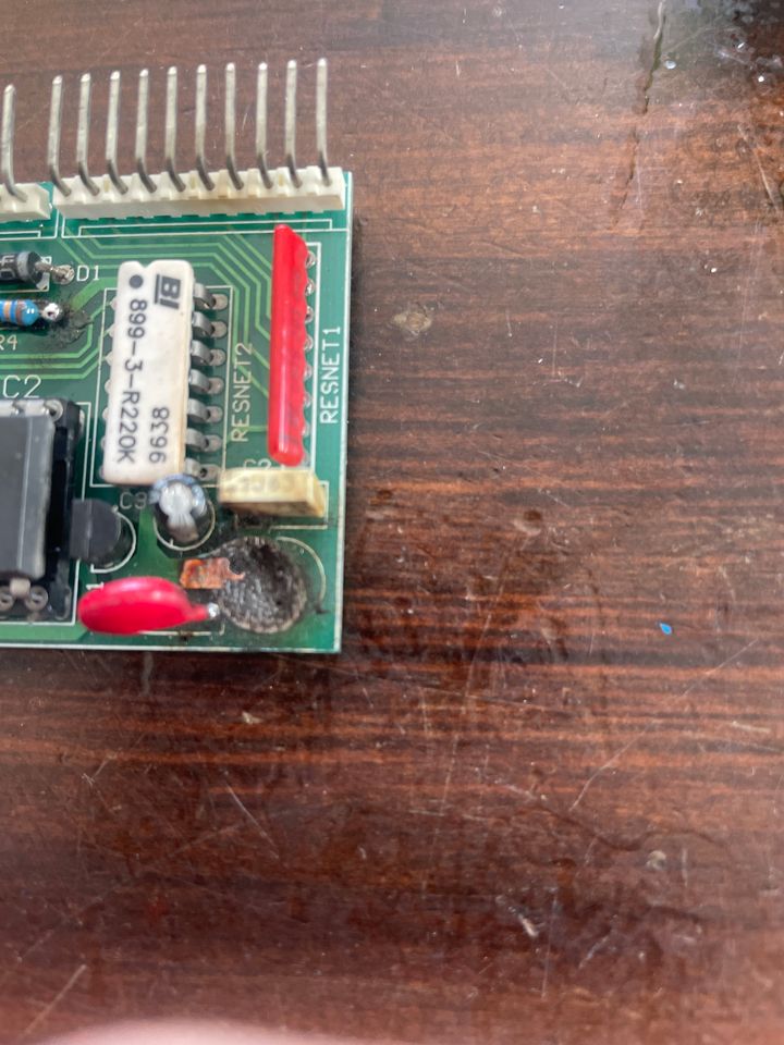
I think you might have asked the wrong person as I didn't see a PM from you?Either way it is a 47uF 35V capacitor - ground connector is closet to the bottom of the board as per silver stripe in picture
HTH Alex
NZ fan said:
Thanks heaps guys. Not sure why it went up in smoke but I ll replace it and see if it all works? Honestly you guys are the only source of this sort of information out there and I appreciate it so much. Thank you for your efforts!!
Pleasure - these boxes are completely unobtainable these days so I luckily managed to collect duplicates of most of them when my electrical system blew up on meOn your board also check R4 as it looks like that might have had a burst of overcurrent as well, as it looks like it was resoldered and slightly melted on the PCB
I think you should count yourself luckily that hopefully the electrolytic capacitor went first before other things blew
This was my board when the darlington arrays got a burst of short circuit and the whole chip exploded...

Luckily there is an ex-TVR tech guy called Paul who is now independant at http://pselectronicsolutions.co.uk/ who managed to fix it very cleverly for me
Forum | Cerbera | Top of Page | What's New | My Stuff