
Headlight / Full beam testing
Discussion


I've got a Cerb riddled with minor electircal faults.
Latest is the headlight full beam not working (I think this was working [albeit 1 light] when first purchased car, but defo isnt working anymore.
Horn works,
Wipers stopped working (But can hear wiper ECU clicking) and think wiper motor seems dead from breif test..
Headlight, nothing - to relay clicking etc..
I've taken the wheel off, and tried briding connections and appears still can't get anything to work, so assume problem is further down.
I've seen the ribbon ends up at a small ECU ontop of the steering colum, with limited access.
Is there an easy way to test that the full beam wiring actually works on both sides, as i'm confident bulbs are OK but beyond that its a mystery. I presume I'd hear a clicking somewhere for the full beam if it was working, I just want to rule out entirely the headlight wiring (which looks janky!) before taking interior apart).
Recently bypassed the Dim / Dip unit as suggested by Python Racing, but still no improvement..
Latest is the headlight full beam not working (I think this was working [albeit 1 light] when first purchased car, but defo isnt working anymore.
Horn works,
Wipers stopped working (But can hear wiper ECU clicking) and think wiper motor seems dead from breif test..
Headlight, nothing - to relay clicking etc..
I've taken the wheel off, and tried briding connections and appears still can't get anything to work, so assume problem is further down.
I've seen the ribbon ends up at a small ECU ontop of the steering colum, with limited access.
Is there an easy way to test that the full beam wiring actually works on both sides, as i'm confident bulbs are OK but beyond that its a mystery. I presume I'd hear a clicking somewhere for the full beam if it was working, I just want to rule out entirely the headlight wiring (which looks janky!) before taking interior apart).
Recently bypassed the Dim / Dip unit as suggested by Python Racing, but still no improvement..
The ecu in the dash reads the various switches and applies some logic then drives other ecu’s
The lights is really just a bunch of relays. I think it’s in the boot. I’d start there and have a listen.
I did reverse engineer the lights ecu, but it looks like I forgot to post on here. I don’t have access to my pc at the moment.
The lights is really just a bunch of relays. I think it’s in the boot. I’d start there and have a listen.
I did reverse engineer the lights ecu, but it looks like I forgot to post on here. I don’t have access to my pc at the moment.
I had posted the circuit of the lights ecu
https://www.pistonheads.com/gassing/topic.asp?h=0&...
Inputs are driven to earth by the wheel ecu.
https://www.pistonheads.com/gassing/topic.asp?h=0&...
Inputs are driven to earth by the wheel ecu.
I've pinned down that its definetly the steering wheel ECU at fault, as grounding the various pin outputs from the steeering ECU with it disconnected all functions correctly, and the buttons have continuity all the way to the ribbon that attached to the steering wheel ECU.
Plus, it was covered in corrision when removed, and looks like other folk have been here before
I'm going to replace this guy (IC3), and his 'holder' as there is plenty of corrosion around here and all try and repair / bridge the incoming feeds from the plug and see if this fixes it...
Beyond that, I'm well out of my depth and will send it away to be repaired properly..
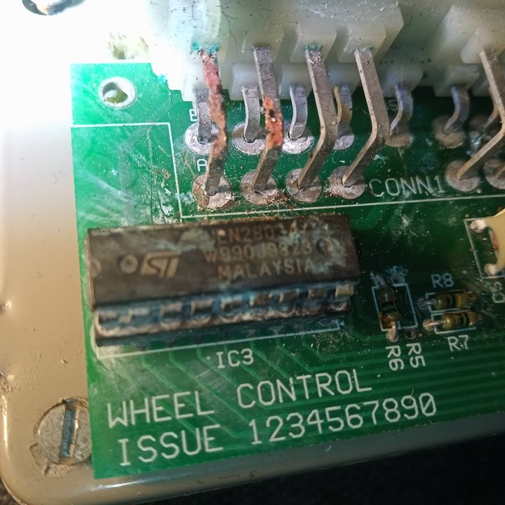
Plus, it was covered in corrision when removed, and looks like other folk have been here before
I'm going to replace this guy (IC3), and his 'holder' as there is plenty of corrosion around here and all try and repair / bridge the incoming feeds from the plug and see if this fixes it...
Beyond that, I'm well out of my depth and will send it away to be repaired properly..
nasty but seen worse
Have you pulled and reseated the IC ?
Personally, I would remove the socket and solder a working IC direct to the PCB in that application.
New IC https://uk.farnell.com/stmicroelectronics/uln2803a...
Have you pulled and reseated the IC ?
Personally, I would remove the socket and solder a working IC direct to the PCB in that application.
New IC https://uk.farnell.com/stmicroelectronics/uln2803a...
Edited by Gary C on Tuesday 10th November 10:45
Forum | Cerbera | Top of Page | What's New | My Stuff