Wanted your broken 5AM
Discussion


Anyone have a faulty 5AM they don't want out there? I want to take a trace waveform of the warm up spike to see if I can replicate the Mark Adams fault diagnosis on slow settle time compared to a good one. Then I can put the two traces together to post on PH when we get " I think my AFM is faulty" posts. Happy to pay postage both ways.
Thanks
Mark
Thanks
Mark
Ive never ever been able to replicate the supposedly correct warm up spike, and on the many occasions when people call me asking to buy a good used afm - citing that their own afm has failed this particular test proceedure - I always tell them to ignore that particular test as it seems to be impossible to replicate the supposed good afm reactions.
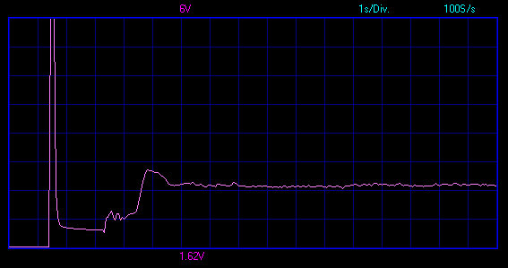
If you could that would be good thanks. Here the start up spike from my AFM that works just fine- as you can see its just 1/2 a second to peak volts because the hot wire is cold, unlike the start that Mark Adams describes over a few seconds- and thats what Im trying to find- then Ill strap a good and "bad" one together on the blower and see if there is a difference in the responses. Its really awkward I cant easily pin down a faulty AFM so far with RoverGauge.

lancepar said:
I lent my AFM to blaze_away to try jonks ago, he said it was broken with a capital F, dunno how he tested it, I didn't need it as the Chim' had MS.

Hi LanceIf my memory can be relied upon.....
I tested it on my car with a digital volt meter. On start up it jumped to 2 volts then slowly decayed to 0.34 over about 30 seconds.
Sir Paolo said:
Hi Mark, I have an AFM you can have.
It’s faulty because I managed to knock lose the loom connector at the top - I’m guessing this renders it useless for testing purposes (otherwise it’s ok )
)
I’ll be posting mine tomorrow/Thursday. If we send both he might be able to make a good one out the two!!It’s faulty because I managed to knock lose the loom connector at the top - I’m guessing this renders it useless for testing purposes (otherwise it’s ok
)

Well thanks to Steve for sending me a duff AFM. This is what I was looking to recreate on a faulty one:
Turn on the ignition, but do not start the engine. The meter should immediately indicate a reading of approximately 0.3-0.34 Volts after the initial "warm up" spike. Most defective airflow meters will overshoot to 0.8 Volts or higher, and take at least 2 seconds to come down to the correct voltage.
So- I was unable to generate the long decay time on the start up spike, but what was clearly visible was the incorrect no airflow voltage:

The green is the good AFM and yellow trace the bad. Note the voltages displayed at the end of the trace of .6 volts on the faulty and .26 volts on the good one.
Then look at the output as i put some air through them-

You can see here the faulty one has a consistently higher output than the good one. This has the effect of over fuelling the engine at lower airflows and idle, although it come back into calibration at higher airflows
Then add some heat into the mix to replicate a TVR engine bay and note the standby voltage:

You will see here the voltage has risen on the bad AFM, but has remained reasonably stable on the green trace and falls into the tolerances given by Mark Adams.
The upshot of all this is not so much look at the decay rate after the initial spike, but the standby voltage, as if this is wrong the whole calibration will be out. I dont think RoverGauge is the best tool to pick up faulty AFMs, as the standby voltage is without a running engine, so RoverGauge wont give you a reading anyway, so Id be sticking to a volt meter and looking for a voltage of below .34 volts on the AFM output.
Turn on the ignition, but do not start the engine. The meter should immediately indicate a reading of approximately 0.3-0.34 Volts after the initial "warm up" spike. Most defective airflow meters will overshoot to 0.8 Volts or higher, and take at least 2 seconds to come down to the correct voltage.
So- I was unable to generate the long decay time on the start up spike, but what was clearly visible was the incorrect no airflow voltage:
The green is the good AFM and yellow trace the bad. Note the voltages displayed at the end of the trace of .6 volts on the faulty and .26 volts on the good one.
Then look at the output as i put some air through them-
You can see here the faulty one has a consistently higher output than the good one. This has the effect of over fuelling the engine at lower airflows and idle, although it come back into calibration at higher airflows
Then add some heat into the mix to replicate a TVR engine bay and note the standby voltage:
You will see here the voltage has risen on the bad AFM, but has remained reasonably stable on the green trace and falls into the tolerances given by Mark Adams.
The upshot of all this is not so much look at the decay rate after the initial spike, but the standby voltage, as if this is wrong the whole calibration will be out. I dont think RoverGauge is the best tool to pick up faulty AFMs, as the standby voltage is without a running engine, so RoverGauge wont give you a reading anyway, so Id be sticking to a volt meter and looking for a voltage of below .34 volts on the AFM output.
Forums | Chimaera | Top of Page | What's New | My Stuff