Alternator Warning Red LED
Discussion


Hi Guys
Just in the process of refitting my dashboard back after changing it back to original,I have fitted an LED for the ignition warning light along with the resistor in parallel across it.
When the engine is started the reading on the voltmeter is 13.5 Volts so alternator is charging but the LED is STILL LIT.I heared that TVR had this problem and built a FUDGING CIRCUIT does anyone know how this worked or how I can get the LED to go out.
Thanks any Help gratefully received
Craig
The ignition light is part of the circuit to start up the excitation of the alternator windings to make it work - you may not be drawing enough current to do this with an LED (if the ignition warning light bulb fails you will find your alternator doesn't work).
And as said above unless its a typo you should have a resistor in series with an LED not parallel, I'm surprised it hasn't gone pop.
And as said above unless its a typo you should have a resistor in series with an LED not parallel, I'm surprised it hasn't gone pop.
I think it works like this :-
There are three wires connected to the alternator, a big thick brown one that is the charge output and goes directly to the battery ( via a fuse ). The other ones are thinner, one is a switched supply ( comes on when the ignition is on ) and energises the coil windings. The third wire drives the charge light. I suspect what happens here is that the alternator pin remains low until it is charging when it becomes high. That way if a lamp is connected with a switched +ve on one side and the alternator charge lamp pin on the other the lamp will light until the alternator pin goes high. In the engine loom these are Grey/White and Brown/Yellow
With an LED you normally put a resistor in series to limit the current. LEDs generally run with a maximum of 1.2v across them, if you exeeed this the current will rise above the maximum the device can handle and it will expire. Just to confuse the issue some LED devices are marked as 12v or 5v this is because they have internal resistors of the appropriate value fitted. It is possible I suppose that the circuit fails to work with just the LED as a load so TVR fitted a resistor in parallel.
steve-V8s said:
I think it works like this :-
There are three wires connected to the alternator, a big thick brown one that is the charge output and goes directly to the battery ( via a fuse ). The other ones are thinner, one is a switched supply ( comes on when the ignition is on ) and energises the coil windings. The third wire drives the charge light. I suspect what happens here is that the alternator pin remains low until it is charging when it becomes high. That way if a lamp is connected with a switched +ve on one side and the alternator charge lamp pin on the other the lamp will light until the alternator pin goes high. In the engine loom these are Grey/White and Brown/Yellow
With an LED you normally put a resistor in series to limit the current. LEDs generally run with a maximum of 1.2v across them, if you exeeed this the current will rise above the maximum the device can handle and it will expire. Just to confuse the issue some LED devices are marked as 12v or 5v this is because they have internal resistors of the appropriate value fitted. It is possible I suppose that the circuit fails to work with just the LED as a load so TVR fitted a resistor in parallel.
I think the two smaller wires you mention are a voltage reference to the battery (the alternator uses this to regulate its output voltage) and the switched ignition feed which excites the coil and powers the no-charge warning light.There are three wires connected to the alternator, a big thick brown one that is the charge output and goes directly to the battery ( via a fuse ). The other ones are thinner, one is a switched supply ( comes on when the ignition is on ) and energises the coil windings. The third wire drives the charge light. I suspect what happens here is that the alternator pin remains low until it is charging when it becomes high. That way if a lamp is connected with a switched +ve on one side and the alternator charge lamp pin on the other the lamp will light until the alternator pin goes high. In the engine loom these are Grey/White and Brown/Yellow
With an LED you normally put a resistor in series to limit the current. LEDs generally run with a maximum of 1.2v across them, if you exeeed this the current will rise above the maximum the device can handle and it will expire. Just to confuse the issue some LED devices are marked as 12v or 5v this is because they have internal resistors of the appropriate value fitted. It is possible I suppose that the circuit fails to work with just the LED as a load so TVR fitted a resistor in parallel.
The no-charge light will be powered forwards if the ignition is on and the alternator isn't charging (e.g. engine not running) and it will be powered backwards if the alternator is charging and the ignition is off (e.g. engine spinning down after being switched off).
So the circuit you're adding needs to cope with about 14V either way.
Usually if you connect an LED to 12V you add a resister in series to limit the current. A 12V LED simply has this resister internally.
Since the no-charge warning light has to supply enough current to kick-start the coils, and an LED typically won't take enough current to do that, you'd need a resister in parallel with your 12V LED to increase the current.
Since LEDs usually don't like having reverse polarity applied you should either have a reversible LED (really two LEDs back to back) or a diode in series with the LED to stop the reverse current. The diode would also stop the LED from glowing if the alternator output is slightly higher than the ignition switched voltage, which can easily happen and is probably the problem the OP has here. The same problem occurs when you use an ordinary filament bulb, but whereas a filament bulb needs a significant current to get hot enough to glow, an LED will glow with any current at all (it just gets dimmer the less current there is).
I have no idea what fix TVR used, but perhaps it was the addition of this diode.
Edited by GreenV8S on Saturday 7th March 18:07
Ive got just a LED a resistor in series on mine, and it all works a treat. The only difference is it takes another 500 rpm to get the LED to go out after youve started it. I think the through current is about 15ma, but lets say the normal filament lamp is 4 watts, its going to pass about 300 ma to start the alternator. So if you cant get the light to go out, you could try wiring something around 120 ohms from the battery connection to the charge wire. This will allow an extra 100 ma to pass that should be enough to get things going, but it will need to be a 2 watt resistor.
The warning light and the field coil are the same wire. 3 wires connected, 2 of them are to the battery & one to the warning light.
Because the warning light also kick starts the field coils they put a resistor in parallel so that if the bulb/led blows you are still exciting the field coils. Modern alternators self excite @2-2500rpm so its not critical I suppose.
The LED light will go off if you switch the blower fans on, its just the normal alt ref V is 12.0V and the dash ignition circuit is @13.8V, the heater fan will draw enough off the dash circuit (can't recall if heater is on dash circuit on Griff - but YSWIM..).
Because of this a bulb is fine, but the LED will need careful selection of a limiting resistor based on its Forward Voltage rating.

I hope nobody minds me joining this thread with my own similar problem. My car has two alternator warning lights, one set in the bottom of the speedo which works normally and one between the speedo and rev. counter which doesn't. This warning light does not light when the ignition is switched on, but only illuminates the instant I turn off the ignition, but just for a fraction of a second. Whilst the engine is running the light is as you would expect off. Could it be that the LED is wired the wrong way round? Any help would be appreciated.
If an LED is a must, this circuit will do the job
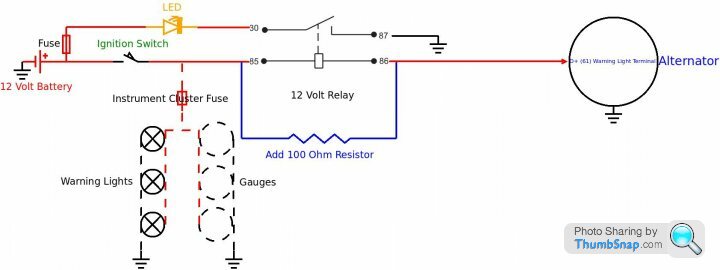
Using Tyco VF4 series 12 volt 40 amp Relay or one of similar specification
Tyco VF4 link - https://www.digikey.co.uk/product-detail/en/te-con...
Coil Resistance - 90 Ohm
Nom Turn On Voltage (Max): 7.2 VDC
Turn Off Voltage (Min): 1.2 VDC
Although the above is named a 12 volt relay its operating voltages are wide apart from 12
12 volt relays have carried on working without problems after withstanding 18 volts for several hours when a vehicles alternator has been overcharging
As can be seen above, the Tyco VF4 series will pull-in at approx 7.2 volts and hold-in down to approx 1.2 volts
Is important to view the chosen relay's specification if not using a Tyco VF4 series as specifications vary from manufacturer to manufacturer
Wiring a 100 ohms resistor in parallel with the Tyco's coil gives
TYCO 90 Ohm Plus 100 Ohm Resistor In Parallel = 47.368 Ohms
Current = 12 divided by 47.368 = 0.2533355 Say 0.25 amps
Wattage = 12 x 0.25 = 3 = Same as the original 3 watt bulb
100 ohm resistor link - https://www.ebay.co.uk/itm/Wirewound-Cement-Resist...
Replacing the original 3 watt bulb with the Tyco relay coil circuit gives approx the same alternator field exciter current
The LED is simply switched to earth through the relay contacts
The relay is energised by forward and reverse voltages
Should an alternator diode fail and apply a voltage to the alternator field with engine not running (ignition off), the LED will warn the driver
The warning lights and gauges circuit's show how the relay earths during a reverse voltage condition with ignition turned off (circuits have been simplified)
rigga said:
You must have an awful lot of time on your hands, searching for old dormant threads, so you can spread your obsession with relays ...... you're very strange.
Don't be sillyAlthough I have never recommended replacing an alternator W/Lt bulb with an LED
Many posters thought the diagram a load of b
 ks when it was first posted several days ago
Topics such as this one that I've recently posted to prove that people are having problems when fitting an LED as an alternator warning light
I thoroughly enjoy solving problems and the fact this latest solution includes a relay doesn't mean I'm obsessed with them in any way
I find it extremely strange that you spend time posting that I'm very strange
Do think you have an agenda though
That said
When I die I am hoping to come back to this world as a relay
No agenda, as said you seem to think people need electrical help, but have resuscitated decade old threads, are they actually in need of help now ? Also you get aggressive when questioned on your ability to actually draw a working diagram that's not overly complicated, with multiple failure points in built, I believe your skill level is in your head only and not based on facts, I recall you have been called out on this several times before, many posters questioning the need for the abundant relays you continually use ...... as I said, strange, and I'm being kind.
rigga said:
No agenda, as said you seem to think people need electrical help, but have resuscitated decade old threads, are they actually in need of help now ? Also you get aggressive when questioned on your ability to actually draw a working diagram that's not overly complicated, with multiple failure points in built, I believe your skill level is in your head only and not based on facts, I recall you have been called out on this several times before, many posters questioning the need for the abundant relays you continually use ...... as I said, strange, and I'm being kind.
Yes agenda, you didn't post any of the above in your earlier postrigga said:
You must have an awful lot of time on your hands, searching for old dormant threads, so you can spread your obsession with relays ...... you're very strange.
You're up for it for the sake of beingThank you for being so kind
A Google Pistonheads search shows results within seconds
Bye bye
Edited by Penelope Stopit on Thursday 9th July 17:06

Sorry to hijack this - I'm doing a MS2 conversion and it seems the grey and white wire has gotten lost somewhere. Is this for the charge LED or exciter?
spitfire4v8 said:
Presumably chimpongas has been banned again ? a load of his posts from the other day have vanished and your post above ^^ now makes no sense because it related to his post.
Yes he's banned for name and shaming.Gassing Station | Griffith | Top of Page | What's New | My Stuff