Indicators affecting VDO voltmeter
Discussion


The following won't cure the volt-drop that's showing on the volt meter, you would need to work through the fused ignition side of the circuit to find that, although it is sometimes found before the fuse-box along the un-fused supply
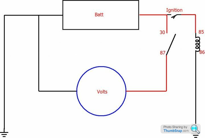
There is a modification that will give you true battery voltage at the volt meter
Add and wire an ignition switched relay, supply the relay terminal 30 contact directly from the battery (fused) and connect terminal 87 of the same relay to the volt-meter positive
Run another cable from battery negative to the volt-meter negative
Your car then becomes one of the few that has true battery voltage at the volt-meter
It's a manufacture thing, they sometimes really don't care to wire correctly
Not meaning to tell Grandmother how to.........
Edited by Penelope Stopit on Monday 2nd September 11:09
Adrian,
ad an earth strap from the bracket where the bonnet pull goes, through the bulkhead grommet, to the engine (I add it at the rear of the offside head where the other earths are congregating).
The cause is the earth being taken through the bonnet release cable which being made of steel....
ad an earth strap from the bracket where the bonnet pull goes, through the bulkhead grommet, to the engine (I add it at the rear of the offside head where the other earths are congregating).
The cause is the earth being taken through the bonnet release cable which being made of steel....
This is a job for later in the week...it is the Rover SD1 column and umbrella handbrake (SEAC interior) BUT, earth checking and the connectors will be done. I will pull an LED version of the flasher relay out to put in (just to see it makes a difference) which I know I have seen somewhere up in the dash hanging off the loom!when the column apart last year (the indicator/wiper switch clamp had been over tightened and it needed to be replaced) Thanks. A@
Thanks Keith..this is MY first TVR ever with VDO and as you say it is 'they are all like that', but in the past no one ever asked me to actually cure it LOL...(Steve, thanks, as and PS say's for the Smiths gauges), but the VDO gauge do not require a stabiliser ).
I will be able to run through a wiring diagram on Wednesday AND test the hazards for fluctuation as I have not checked those (whilst the engine is running) or seen a relay (is that hanging on the loom somewhere? anyone).
A@
I will be able to run through a wiring diagram on Wednesday AND test the hazards for fluctuation as I have not checked those (whilst the engine is running) or seen a relay (is that hanging on the loom somewhere? anyone).
A@
Edited by Adrian@ on Monday 2nd September 21:33
The same issue has been bugging me for a while so this post kicked me into action to investigate this morning.
The cause of the problem is that the flasher is wired to the same 12V feed as the voltmeter (and the other gauges), such that when the indicators are activated, there is around a 1 volt drop as measured across the 12V feed at the flasher unit when active. With the ignition on, but indicators off, there is only about 0.1V difference between the voltage measured directly across the battery and across the flasher unit.
Also measured the resistance in both the 12V and earth lines from the battery to the flasher unit and only a couple of ohms in each, so no major issues with the circuit.
As a test I tried running a temporary earth from the battery to the flasher unit but it made no noticeable difference in my case.
I then tried disconnecting the 12V feed to the flasher unit and wiring in a direct feed from the battery. Problem solved, except the flasher circuit is active all the time of course.
Without taking the dash out and rewiring with bigger gauge cable, it seems to me that simply separating out the 12V feed to the voltmeter from the feed to flasher unit is the easiest work-around. Penelope Stopit’s solution above will work fine, as will a similar circuit in the 12V feed to the flasher unit. I’m going for the latter as that does not require any work behind the dash.
A fused relay is on order.
Brilliant, I have just looked and the flasher relay is hung above the steering wheel having been re wired away from the fuse board..so I need maybe just put it back on the relay board! I note that the flashers are way more dramatic with their fluctuation than the hazards. Thanks. A@
Edited by Adrian@ on Tuesday 3rd September 16:31

Adrian@ said:
Brilliant, I have just looked and the flasher relay is hung above the steering wheel having been re wired away from the fuse board..so I need maybe just put it back on the relay board! I note that the flashers are way more dramatic with their fluctuation than the hazards. Thanks. A@
My indicator unit is up besides the steering column too, so doubt if yours has been moved. And yes, I only see the voltmeter move with the indicators, not the hazards....Edited by Adrian@ on Tuesday 3rd September 16:31
Adam, I have used this diagram.
http://tvr.me.uk/TVRelEn.gif (is there better...)
and everything ran pretty much as this (mine is as such a USA spec car) ...if it is 'remoted' off the board then it is going back and a proper Piezo buzzer can go behind the dash. I wish I had hearing enough to hear it clicking. A@
http://tvr.me.uk/TVRelEn.gif (is there better...)
and everything ran pretty much as this (mine is as such a USA spec car) ...if it is 'remoted' off the board then it is going back and a proper Piezo buzzer can go behind the dash. I wish I had hearing enough to hear it clicking. A@
I have found that the remoted relay is the fuel pump relay. The holder has got hot as some point and the (pink) relay has been tucked up under the dash, I will need to put that back into place with new soldered connections before I move onto the indicators... and finish fitting the dash cam at the same time. A@
Gassing Station | Wedges | Top of Page | What's New | My Stuff