Discussion


As discussed new thread to discuss my seemingly numerous problems.
In response to some of latest comments on sparking priblem
1988 350i Lucas 4cu flapper 2am AFM, older rev counter, ECU and AFM just rebuilt by ATP so I'm gonna rule out these now being faulty as the company seem to know what they are talking about. Car now sparking and timing near as dammit, now seems to be little or no fuel getting into cylinders, fuel pump working fine off AFM flap. Pressure checked and good. This was fueling before I started messing with the electrics trying to solve the spark problem. Running tests on components and pins 18 and 3 to t pot only 0.75v and 6,9 to AFM same, believe these should be 4.5v. earth's all been rebuilt and very good throughout car all other electrics working spot on. Going to work through wiring again but always open to suggestions.
And that's where the problems started. From the beginning I purchased this 18 months ago as part restoration, new chassis up most if the mechanics done and a fair job of most but an old guy and getting the engine running had defeated him, spent 3 months completing and got engine running, not as smoothly as I wanted but running. There was a problem with diff that I didn't want to tackle on my back so sent to a TVR specialist for diff, tune up health check and mot. 6 months later I was still making calls trying to get it back, they were struggling to get it running right, we agreed to trailor it back. Never started since, despite them saying they drove it on to the trailor, that's 4 weeks ago. Assumed as it was apparently running something had shaken loose on the way back so started with all the obvious and here we are. Im obviously questioning if they had it running. Not going to start naming them as I don't think they are wrong uns, just got lost with it. So it won't be going out of my sight again.
Bigfish_74 said:
And that's where the problems started. From the beginning I purchased this 18 months ago as part restoration, new chassis up most if the mechanics done and a fair job of most but an old guy and getting the engine running had defeated him, spent 3 months completing and got engine running, not as smoothly as I wanted but running. There was a problem with diff that I didn't want to tackle on my back so sent to a TVR specialist for diff, tune up health check and mot. 6 months later I was still making calls trying to get it back, they were struggling to get it running right, we agreed to trailor it back. Never started since, despite them saying they drove it on to the trailor, that's 4 weeks ago. Assumed as it was apparently running something had shaken loose on the way back so started with all the obvious and here we are. Im obviously questioning if they had it running. Not going to start naming them as I don't think they are wrong uns, just got lost with it. So it won't be going out of my sight again.
Can you rule bad fuel out?Here is a diagram that I put together in 1918 to help someone
What it does is remove the pain of tracing through a full diagram
This diagram also helps simplify the explanation of operation
I may be right, I may be crazy, I am hoping that this matches up to your vehicles wiring
It's difficult at times playing the guessing game online
Does your vehicle have a red coloured Pektron unit (Have mistakenly named it a Plektron in the diagram)
I am also hoping that the person who thinks I don't know what I'm doing keeps out of this for a while as he/she is still not prepared to admit to the rubbish he/she has posted in that other topic. It's all been hilarious for me but..........he/she is on a mission
Now that's out of the way, take a look at below diagram, will be back later to add to this
Have fingers crossed here, click to go big and bigger

Earths at ECU 16, 17 and 35

Check the voltage at the brown battery supply to the injection relay
Injection relay supplies ECU @ Pin 10 - Check this voltage
That injection relay is drawn keeping it simple, very likely to be seperate terminals for relay outputs, one for ECU Pin 10 and another for AFM and onwards to resistor bank
Back to the moronic posts from my friend in the other topic 10.5 Volts is ok hey
It can be seen that the coil supply that needs to be as close as possible to battery voltage very likely continues onwards to control the fuel pump and injection relays via the pektron unit
If the ECU output voltages are definitely wrong, check that ECU pin 10 supply and earths
Does the fuel pump run when cranking?
Ignore all posts that mention pull this pull that, if you play around too much you may fix a fault and not find it again until breakdown time
No good electricians pull everything out hoping to get a fix
Slowly slowly logical thinking and testing is the way to go
I assure you that many posters here will not even bother to comment that the relay and coil voltages need to be close as possible to 12 volts, it would be an admission of messing about in the other topic
Bombing you with information, it's the only way, back later
Wherever you read steering relay or steering module what's meant is the Pektron
Below is a description of operation
Introduction and Location
The Rover SD1 Efi Steering Module activates the Main (Efi) and Fuel Pump relays in a safe sequence and routes power to other key components.
Mounted on the smaller bracket with the relays behind the passenger glove box, it usually has a red plastic cover.
The Main and Fuel Pump Relays are intimately involved with the purpose and function of the Steering Module.
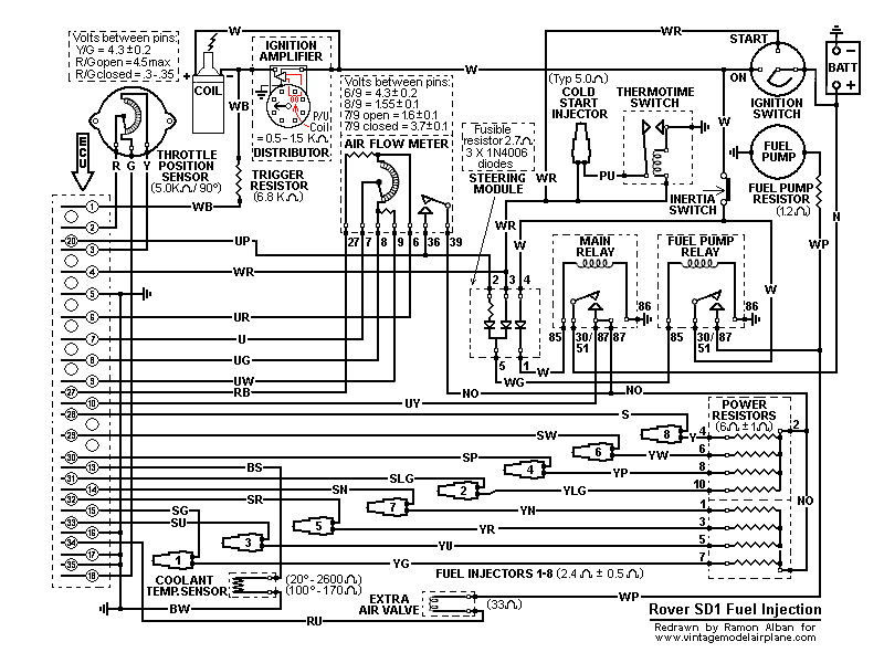
Circuit Diagram
This shows component connections together with their identity in the adjacent list. The Efi Steering Module derives its name from its function of routing power according the mode of operation.
Component Identity
SM Steering Module
MR Main relay
FPR Fuel Pump relay
BATT Battery
IS Ignition switch
FP Fuel Pump
EAV Extra air valve
AFM Air flow meter

Operation
The white (W) wire from the ignition switch supplies power through the right hand diode in the Steering Module (terminals 4 to 1) seen above. From there it connects to terminal 85 of the Main relay, through the relay windings to earth via terminal 86 to close the contacts when energised.
Power is now available directly from the battery via terminals 30/51 and 87 to the air flow meter (Fuel Pump contacts), Pin 10 of the ECU and to the Power Resistors which connect to the fuel injectors. However, current can only energise the injectors when the ECU completes their circuits to earth with appropriately timed injection pulses.
The Fuel Pump relay is also activated through the Steering Module but in two different modes. Initially, in engine cranking mode, power is available to the Steering Module terminal 3 via the white/red (WR) wire from the ignition switch cranking circuit. Then, as the engine starts, in engine running mode, power reaches terminal 2 via the blue/purple (UP) wire coming from the now closed Fuel Pump contacts inside the Air Flow Meter, also connected to Pin 20 of the ECU.
In either mode, current passes from the Steering Module via the respective diodes at terminal 5 to the Fuel Pump relay terminal 85, through the relay windings to earth. The closed relay contacts operate both the Fuel Pump and the Extra Air Valve with power drawn from the ignition switch.
These two diodes, by their nature of preventing current from flowing in the reverse direction, ensure that operating current from terminal 3 cannot pass to terminal 2 and vice versa.
In summary, the Fuel Pump is initially energised in the cranking mode but as soon as the engine draws air through the air flow meter its internal Fuel Pump contacts close, completing the alternative circuit to keep the Fuel Pump energised until either the ignition is switched off or the engine stalls, the Air Flow Meter flap closes, thus opening its internal Fuel Pump contacts.
The above operational description is limited to the immediate circuitry of the subject components but a complete Rover SD1 Efi circuit diagram may also help:
Reliabilty and Replacement
Components in the Rover SD1 Efi System have varying degrees of reliability but the Steering Module has proved, over time, to be a very robust item not prone to chronic failure. One hears anecdotal evidence of failure but they seem to coincide with injudicious poking around with meter probes elsewhere in the system that cause short circuits capable of damaging the internal diodes.
The diodes, type 1N4006, are straight forward items readily available from semiconductor vendors at low cost and can be easily tested/replaced. However the fourth component in the module is an unusual fusible resistor, rated at 2.7 Ohms. Because it is an ECU protection and safety item it must be replaced "like for like". Replacements are inexpensive but will be harder to find.
To that end, and due to low failure rate, one often sees used Modules and Relays at Club Spares Days. Also SD1 Ebayers and Land/Range Rover S/H spares suppliers would readily provide them.
Conclusions
Because of its strange name and relative inaccessibility, the Steering Module and the associated relays have a reputation of unwarranted mysticism, whereas, in fact, it simply makes sure that the Main and Fuel Pump relays operate correctly and safely during the cranking and running modes.
There is loads more about the Flapper Efi system here
What it does is remove the pain of tracing through a full diagram
This diagram also helps simplify the explanation of operation
I may be right, I may be crazy, I am hoping that this matches up to your vehicles wiring
It's difficult at times playing the guessing game online
Does your vehicle have a red coloured Pektron unit (Have mistakenly named it a Plektron in the diagram)
I am also hoping that the person who thinks I don't know what I'm doing keeps out of this for a while as he/she is still not prepared to admit to the rubbish he/she has posted in that other topic. It's all been hilarious for me but..........he/she is on a mission
Now that's out of the way, take a look at below diagram, will be back later to add to this
Have fingers crossed here, click to go big and bigger
Earths at ECU 16, 17 and 35
Check the voltage at the brown battery supply to the injection relay
Injection relay supplies ECU @ Pin 10 - Check this voltage
That injection relay is drawn keeping it simple, very likely to be seperate terminals for relay outputs, one for ECU Pin 10 and another for AFM and onwards to resistor bank
Back to the moronic posts from my friend in the other topic 10.5 Volts is ok hey
It can be seen that the coil supply that needs to be as close as possible to battery voltage very likely continues onwards to control the fuel pump and injection relays via the pektron unit
If the ECU output voltages are definitely wrong, check that ECU pin 10 supply and earths
Does the fuel pump run when cranking?
Ignore all posts that mention pull this pull that, if you play around too much you may fix a fault and not find it again until breakdown time
No good electricians pull everything out hoping to get a fix
Slowly slowly logical thinking and testing is the way to go
I assure you that many posters here will not even bother to comment that the relay and coil voltages need to be close as possible to 12 volts, it would be an admission of messing about in the other topic
Bombing you with information, it's the only way, back later
Wherever you read steering relay or steering module what's meant is the Pektron
Below is a description of operation
honestjohntoo said:
Ian350 said:
I think this is playing up --- It is the red relay in the corner of the fuse board. It seems to control the fuel pump - when it feels like it.
It may help you to understand how the steering module does its work.Introduction and Location
The Rover SD1 Efi Steering Module activates the Main (Efi) and Fuel Pump relays in a safe sequence and routes power to other key components.
Mounted on the smaller bracket with the relays behind the passenger glove box, it usually has a red plastic cover.
The Main and Fuel Pump Relays are intimately involved with the purpose and function of the Steering Module.
Circuit Diagram
This shows component connections together with their identity in the adjacent list. The Efi Steering Module derives its name from its function of routing power according the mode of operation.
Component Identity
SM Steering Module
MR Main relay
FPR Fuel Pump relay
BATT Battery
IS Ignition switch
FP Fuel Pump
EAV Extra air valve
AFM Air flow meter
Operation
The white (W) wire from the ignition switch supplies power through the right hand diode in the Steering Module (terminals 4 to 1) seen above. From there it connects to terminal 85 of the Main relay, through the relay windings to earth via terminal 86 to close the contacts when energised.
Power is now available directly from the battery via terminals 30/51 and 87 to the air flow meter (Fuel Pump contacts), Pin 10 of the ECU and to the Power Resistors which connect to the fuel injectors. However, current can only energise the injectors when the ECU completes their circuits to earth with appropriately timed injection pulses.
The Fuel Pump relay is also activated through the Steering Module but in two different modes. Initially, in engine cranking mode, power is available to the Steering Module terminal 3 via the white/red (WR) wire from the ignition switch cranking circuit. Then, as the engine starts, in engine running mode, power reaches terminal 2 via the blue/purple (UP) wire coming from the now closed Fuel Pump contacts inside the Air Flow Meter, also connected to Pin 20 of the ECU.
In either mode, current passes from the Steering Module via the respective diodes at terminal 5 to the Fuel Pump relay terminal 85, through the relay windings to earth. The closed relay contacts operate both the Fuel Pump and the Extra Air Valve with power drawn from the ignition switch.
These two diodes, by their nature of preventing current from flowing in the reverse direction, ensure that operating current from terminal 3 cannot pass to terminal 2 and vice versa.
In summary, the Fuel Pump is initially energised in the cranking mode but as soon as the engine draws air through the air flow meter its internal Fuel Pump contacts close, completing the alternative circuit to keep the Fuel Pump energised until either the ignition is switched off or the engine stalls, the Air Flow Meter flap closes, thus opening its internal Fuel Pump contacts.
The above operational description is limited to the immediate circuitry of the subject components but a complete Rover SD1 Efi circuit diagram may also help:
Reliabilty and Replacement
Components in the Rover SD1 Efi System have varying degrees of reliability but the Steering Module has proved, over time, to be a very robust item not prone to chronic failure. One hears anecdotal evidence of failure but they seem to coincide with injudicious poking around with meter probes elsewhere in the system that cause short circuits capable of damaging the internal diodes.
The diodes, type 1N4006, are straight forward items readily available from semiconductor vendors at low cost and can be easily tested/replaced. However the fourth component in the module is an unusual fusible resistor, rated at 2.7 Ohms. Because it is an ECU protection and safety item it must be replaced "like for like". Replacements are inexpensive but will be harder to find.
To that end, and due to low failure rate, one often sees used Modules and Relays at Club Spares Days. Also SD1 Ebayers and Land/Range Rover S/H spares suppliers would readily provide them.
Conclusions
Because of its strange name and relative inaccessibility, the Steering Module and the associated relays have a reputation of unwarranted mysticism, whereas, in fact, it simply makes sure that the Main and Fuel Pump relays operate correctly and safely during the cranking and running modes.
There is loads more about the Flapper Efi system here
Edited by Penelope Stopit on Wednesday 17th June 17:57
Edited by Penelope Stopit on Wednesday 17th June 18:01
I assume you guys have seen this and the horror stories of what goes wrong with the 4CU, especially the bit about the dry joints ....
http://www.vintagemodelairplane.com/pages/Download...
http://www.vintagemodelairplane.com/pages/Download...
blitzracing said:
I assume you guys have seen this and the horror stories of what goes wrong with the 4CU, especially the bit about the dry joints ....
http://www.vintagemodelairplane.com/pages/Download...
Nice, was going to post that laterhttp://www.vintagemodelairplane.com/pages/Download...
It's not something daft like a worn wire on one of the sensors? For those that haven't seen it before here's a photo that Mark has shown many times in the past but does demonstrate that wires hidden away behind the boots can wear and then short out. This is the coolant temperature sensor connector.

So engine has a big fat spark - check.
Assuming big fat spark is timed correctly? Static test would prove this.
Engine has a working fuel pump and fuel to the rail - check
When cranked then no fuel getting into the cylinders? - check for wet plugs or at least the smell of fuel?
If the AFM is given the finger then fuel pump definitely runs?
I cant remember the test for listening to the injectors clicking. Can someone remind me?
ECU and AFM inspected and confirmed healthy by specialist - check
So if the HT system, fuel system and ECU individually appear to be working then could it be a hard wire issue/bad connection/buggered relay?
Also back to basics - is there compression? Are the valves opening and closing? Is it definitely timed to TDC? if the dissy has been pulled then it could be 180 degrees out? Would be worth pulling No1 spark plug, rotating the engine to confirm TDC (pressure on the up-stroke) and then checking that the rotor arm is aligned to No 1 HT lead.
Also for peace of mind pull every damn fuse and double check they are all good with a multimeter and do not have corroded contacts.
Edited by KKson on Wednesday 17th June 17:27
Edited by KKson on Wednesday 17th June 17:29
KKson said:
It's not something daft like a worn wire on one of the sensors? For those that haven't seen it before here's a photo that Mark has shown many times in the past but does demonstrate that wires hidden away behind the boots can wear and then short out. This is the coolant temperature sensor connector.
So engine has a big fat spark - check.
Assuming big fat spark is timed correctly? Static test would prove this.
Engine has a working fuel pump and fuel to the rail - check
When cranked then no fuel getting into the cylinders? - check for wet plugs or at least the smell of fuel?
If the AFM is given the finger then fuel pump definitely runs?
I cant remember the test for listening to the injectors clicking. Can someone remind me?
ECU and AFM inspected and confirmed healthy by specialist - check
So if the HT system, fuel system and ECU individually appear to be working then could it be a hard wire issue/bad connection/buggered relay?
Also back to basics - is there compression? Are the valves opening and closing? Is it definitely timed to TDC? if the dissy has been pulled then it could be 180 degrees out? Would be worth pulling No1 spark plug, rotating the engine to confirm TDC (pressure on the up-stroke) and then checking that the rotor arm is aligned to No 1 HT lead.
Also for peace of mind pull every damn fuse and double check they are all good with a multimeter and do not have corroded contacts.
That's my conclusion kk, all the mentioned previously checked and good so working through the wiring again next job, cheers
Edited by KKson on Wednesday 17th June 17:27
Edited by KKson on Wednesday 17th June 17:29
Penelope Stopit said:
Edited by Penelope Stopit on Wednesday 17th June 17:57
Edited by Penelope Stopit on Wednesday 17th June 18:01
I see we're "going all in".
So some reasonable posts above. I would also like to point out that the ECU gets trigger pulses from the ignition circuit, so this must be working for the injectors to fire when the engine rotates.
A useful test of the injectors themselves is:
1. Turn on ignition.
2. Go to the throttle butterfly.
3. Rotate throttle butterfly quickly through at least 45 degrees by hand.
4. The injectors should click audibly.
This method tests the auto enrich feature of the 4CU.
The 4CU will put up with quite a low battery voltage, or else how would we ever start our cars! So make sure you're at or around 9V across the battery when cranking. If higher, so much so good.
With all the starting attempts and no spark you may have wet the spark plugs, so take them all out, and let them dry overnight. (I've heard some old wives tales that they will be junk, but in 30+ years Rv8 experience, they are fine after being dried off)
Penelope Stopit said:
Almost forgot to mention
The poster above can supply you with a replacement Pektron, he makes them in his cave
I know that, and a jolly nice and helpful chap he is to. Anyone who uses his ultra rare supercharged Wedge as his daily driver in all weathers gets my respect....... The poster above can supply you with a replacement Pektron, he makes them in his cave

adam quantrill said:
I see we're "going all in".
So some reasonable posts above. I would also like to point out that the ECU gets trigger pulses from the ignition circuit, so this must be working for the injectors to fire when the engine rotates.
A useful test of the injectors themselves is:
1. Turn on ignition.
2. Go to the throttle butterfly.
3. Rotate throttle butterfly quickly through at least 45 degrees by hand.
4. The injectors should click audibly.
This method tests the auto enrich feature of the 4CU.
The 4CU will put up with quite a low battery voltage, or else how would we ever start our cars! So make sure you're at or around 9V across the battery when cranking. If higher, so much so good.
With all the starting attempts and no spark you may have wet the spark plugs, so take them all out, and let them dry overnight. (I've heard some old wives tales that they will be junk, but in 30+ years Rv8 experience, they are fine after being dried off)
Thanks Adam, No click on the enrichment and no click when cranking and a pipe held to injector and my ear. Plugs dried and cleaned and sparking ok so I've lost the Signal to injectors somewhere, Pektron and relays next thing to look at for fault.So some reasonable posts above. I would also like to point out that the ECU gets trigger pulses from the ignition circuit, so this must be working for the injectors to fire when the engine rotates.
A useful test of the injectors themselves is:
1. Turn on ignition.
2. Go to the throttle butterfly.
3. Rotate throttle butterfly quickly through at least 45 degrees by hand.
4. The injectors should click audibly.
This method tests the auto enrich feature of the 4CU.
The 4CU will put up with quite a low battery voltage, or else how would we ever start our cars! So make sure you're at or around 9V across the battery when cranking. If higher, so much so good.
With all the starting attempts and no spark you may have wet the spark plugs, so take them all out, and let them dry overnight. (I've heard some old wives tales that they will be junk, but in 30+ years Rv8 experience, they are fine after being dried off)
Pektron contains silicon diodes so you can expect about 0.6V difference between input and output (when they are conducting - it won't allow reverse flow).
So your measurements seem OK. Pektron output only feeds the relay coils anyway which probably pull over at ~8V and hold lower than that probably ~5V.
My version has fatter diodes and slightly less volts drop for the same current draw. However none in stock right now I'd have to crank up the 3D printer!
Edited by adam quantrill on Thursday 18th June 14:39
Other obvious stuff to check:
make sure the resistor pack is plugged in. You can check it with an ohmmeter (it's the smaller silver box in the engine bay). Or else no injector clicks.
make sure the ECU is plugged in properly, the silver retaining tang on the multiplug should keep it attached, but sometimes this needs bending towards the socket to make it engage.
What's your battery voltage during cranking? You only need the first few seconds, don't overdo it.
Edited by adam quantrill on Thursday 18th June 10:27
Bigfish_74 said:
Position 1 at Pektron white wire reads only 11.7v, ,12.6v at brown and brown orange on injector relay(main), changed the wire no change.
Not forgetting that low voltages do cause problems and need sortingand
Thinking ahead about the future solving of the ignition coil supply volt-drop that has been improved a little
The present measured voltages need to be noted as they may well help in solving the coil supply volt-drop
Note the following for future reference
The 11.7 volts @ Pektron terminal 1 tells us that the white ignition supply at Pektron terminal 4 will be above 12 volts
Diagrams show that the white ignition supply @ Pektron terminal 4 (above 12 volts) is of the same supply source as the ignition coil supply that was previously measured as 11 volts
Are they common? Perhaps they are, diagrams show that they are
[b]There is a possibility that the ignition supply to ignition coil is not from the same source as the Pektron supply. Coil supply from relay through rev counter seems to be what you have but can't be sure, possibly Pektron supply directly from the ignition switch
Now that the above has been noted
Moving on
Don't be too concerned at present about the relay coils control voltages from the Pektron, relays will switch on with several volts and stay on with (2or3or4or5 volts)
Bigfish_74 said:
12.6v at brown and brown orange on injector relay(main)
That's very high, very goodIs there a battery charger connected?
Would have been interesting to know what the battery voltage was when checking the relay voltages
Bigfish_74 said:
changed the wire no change.
Don't know what you mean by thatSupply @ ECU Pin 10 from the injection relay is the voltage that you need to measure
Check ECU earth voltages
If all is good follow suggested faults from those that have pointed out that possible shorts @ the injection loom plugs or elsewhere will cause a problem
Bigfish_74 said:
Thanks Adam, No click on the enrichment and no click when cranking and a pipe held to injector and my ear. Plugs dried and cleaned and sparking ok so I've lost the Signal to injectors somewhere, Pektron and relays next thing to look at for fault.
For this specific test result it's also worth checking the 3 wires at the throttle pot. One is ground, one is wiper and one is reference +V (4.5 as I recall?) from the ECU. If the reference is not coming out, then the ECU is either not supplying it or it's shorted to ground somewhere. The latter fault can also stop the ECU from running. The wiper connection should vary smoothly as you rotate the pot. If all looks OK check the throttle closed voltage is ~0.325V on the wiper connection. You can rotate the pot to set this. This isn't critical for starting but you may as well while you're there.
Gassing Station | Wedges | Top of Page | What's New | My Stuff