I just re-engineered my rev counter to work off Megasquirt!
Discussion


Have been struggling a lot to make my bloody rev counter work with the MS2-extra... Nothing has been working, so eventualy I took the plunge and stripped the instrument to see what makes it tick. Boggo SN76810P tacho driver IC. Got the datasheet and worked out how the circuit board worked. Input on Pin 2 of the IC should be something like a square wave as the driver is edge triggered.
There's all sorts of rubbish tacked onto the input pin, like a miniature transformer, a capacitor and 2 resistors and other guff. So I strip pin 2 of all that nonsense, and give it a simple square wave off my rough-arse breadboard square wave generator, and as expected, it now works.
So, if you've read this far you clearly have a major interest in this tosh [or you'd surely have gone and opened a beer by now and be watching Top Gear on Dave], so that is how to make a wedge rev counter work with Megasquirt. Remove bezel, glass, needle, unscrew fascia, drill 3 rivets out the back and desolder R2, R3 and C3 and move the white wire to any of the now vacant through holes connected to pin 2 of the 76810P. You now have a rev counter that works off a square wave. MS2e tacho driver pin is a switched ground, so pull it to ignition live with a 4k7 resistor and connect it to the rev counter.
Woohoo!
What a nerd...


Wedg1e said:
Sounds fair enough to me 
Good to see that some of the old knowledge is still about; every time we advertise for electronics staff we get 'engineers' who can swap boards till the fault goes away but show them a soldering iron and they poo their pants...
We get that a lot too when we call an engineer out to our alarm systems at work. "Ah It's just the mainboard so I will swap that over for you"Good to see that some of the old knowledge is still about; every time we advertise for electronics staff we get 'engineers' who can swap boards till the fault goes away but show them a soldering iron and they poo their pants...
Two weeks later and we are ussually on the 5th engineer and 10th mainboard before one of them pulls out a soldering iron and fixes it.
I'm going to get over the issue by installing a completly digital dash with rev, speedo, fuel, warning lights etc . A bit like this one
http://cgi.ebay.co.uk/ws/eBayISAPI.dll?ViewItem&am...
Then will be putting in some digital dual guages in the centre console which will hopefull give a bit more info
This then saves me trying to source all the original bits
http://cgi.ebay.co.uk/ws/eBayISAPI.dll?ViewItem&am...
Then will be putting in some digital dual guages in the centre console which will hopefull give a bit more info
This then saves me trying to source all the original bits
Ed, snap! I have been doing exactly the same for the revcounter on my Chim 400 after going down the Megasquirt route, was the original PCB SMD on your instrument? Mine was and I got fed up tracing & modifying the circuit so I started from scratch with a sinmple 555 circuit. Biggest problem I had was getting the damping right, it would seem that the mechanics of the moving coil mech on my unit is grossly underdamped, it is almost as though some part has dropped off!
All sorted now though.
Andy.
Apprentice nerd
Edited by lotusandy on Thursday 3rd June 08:51
Hi all,
there is another option that seems to work with the original tachos on the Griffs and Chims, in fact its for tachos that were fired off the coil -ve.
It's 4 IN4004 diodes and a 15-22V zener connected to the coil packs.
As I mustn't upset anyone and blatently plug a certain ECU that begins with M all I can say is, if anyone bought an ECU from someone who's name begins with P and ends in P from a company beginning with E then he will supply you one for free to play with, if that makes sence
Phil
Bloody hell you should have asked, I went through the same mod about a month ago !
I just cut the tracks to the current transformer, connected the white wire to the output pin of the transformer via a 1K resistor, then added a 12v Zener to ground to limit the input voltage to the IC.
Tests on a pulse generator showed that using this mod the tach triggered correctly from a inout signal as low as 3v. Also found out the that SW tach is really slow to react to increasing RPM, my shift light trips well before the needle gets anywhere near the setpoint, but if I hold the revs it does catch up eventually.
Edited by B@man on Thursday 3rd June 11:18
I fired it up again this morning, and as I raise the supply voltage on the PSU it does some weird things, and doesn't really work properly until it gets a good 13 volts and then the reading on the gauge rises with supply voltage. I'll pop it on the car this evening, and if it doesnt work, I may either implement the B@tman mod, or build a new circuit with the new version of 76810P - the LM2907.
Phil, thankyou for your help with the diode circuit, but with my setup I found it just made the car misfire like mad, which I really dont understand, but hey! when I get it sorted I'll let you know what I did.
Incidentally, the Stewart Warner tacho looks like a moving coil type. Does anyone know whether moving coils should be driven by current control method, or voltage control method?
I would suspect current control method as I reckon the armature resistance will be pretty low?
Lotusandy,
Nah, mine is good old thru-pin, but I believe Wedge tachos are a different beast to the later stuff. Believe the later tachos are made by Smiths too? And function off the switched side of the coil as is sensible?!?
Edited by ed_crouch on Thursday 3rd June 12:05
ed_crouch said:
I fired it up again this morning, and as I raise the supply voltage on the PSU it does some weird things, and doesn't really work properly until it gets a good 13 volts and then the reading on the gauge rises with supply voltage. I'll pop it on the car this evening, and if it doesnt work, I may either implement the B@tman mod, or build a new circuit with the new version of 76810P - the LM2907.
Phil, thankyou for your help with the diode circuit, but with my setup I found it just made the car misfire like mad, which I really dont understand, but hey! when I get it sorted I'll let you know what I did.
Incidentally, the Stewart Warner tacho looks like a moving coil type. Does anyone know whether moving coils should be driven by current control method, or voltage control method?
I would suspect current control method as I reckon the armature resistance will be pretty low?
Lotusandy,
Nah, mine is good old thru-pin, but I believe Wedge tachos are a different beast to the later stuff. Believe the later tachos are made by Smiths too? And function off the switched side of the coil as is sensible?!?
The Smiths tachos I used to modify were 0 to 10mA. Theres actually a circuit on my site for modifying the tacho over to a frequency convertor, see here: http://www.extraefi.co.uk/cobra/accobra.htm find Rev Counter on the left hand side,Phil, thankyou for your help with the diode circuit, but with my setup I found it just made the car misfire like mad, which I really dont understand, but hey! when I get it sorted I'll let you know what I did.
Incidentally, the Stewart Warner tacho looks like a moving coil type. Does anyone know whether moving coils should be driven by current control method, or voltage control method?
I would suspect current control method as I reckon the armature resistance will be pretty low?
Lotusandy,
Nah, mine is good old thru-pin, but I believe Wedge tachos are a different beast to the later stuff. Believe the later tachos are made by Smiths too? And function off the switched side of the coil as is sensible?!?
Edited by ed_crouch on Thursday 3rd June 12:05
Phil
ed_crouch said:
Phil, thankyou for your help with the diode circuit, but with my setup I found it just made the car misfire like mad, which I really dont understand, but hey! when I get it sorted I'll let you know what I did.
Possibly something to do with the back-emf spikes exceeding the PIV of the diodes? Crappy Chinese diodes with insulation breakdown?Interesting as I use the 4 diode trick to trigger Lucas the clockwork box under the dash and it seems quite happy, to be fair it doesn't have much choice !
The problem with the 400 / 450 tacho's is that they where current driven and use a small transformer to pick up a voltage pulse from current spikes on the coil feed. The 350 / 390 are all pulse driven off the coil -ve in the normal post 1960's manner.
With the 400 / 450 tach once you bypass the current to voltage bit the circuit is quite happy with any square-ish waveform, I tested it with very short "spikes" up to a 50% square wave and it was a happy chappy
It's a hell of lot easier than making a mk2 escort tach work off from a Ford sierra diesel
alternator
Modified SW Tach board
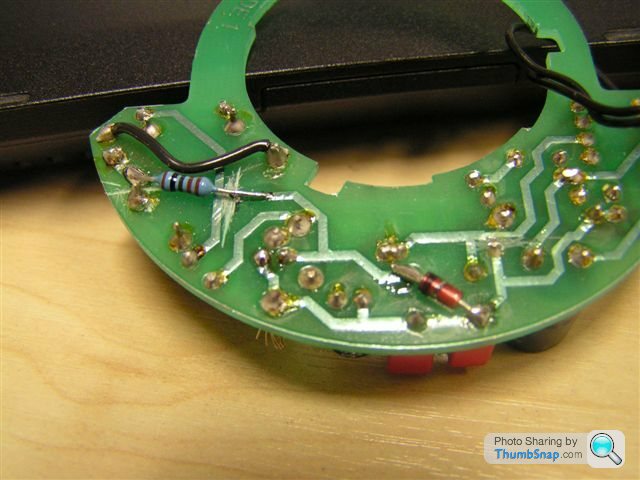
Testing it

The problem with the 400 / 450 tacho's is that they where current driven and use a small transformer to pick up a voltage pulse from current spikes on the coil feed. The 350 / 390 are all pulse driven off the coil -ve in the normal post 1960's manner.
With the 400 / 450 tach once you bypass the current to voltage bit the circuit is quite happy with any square-ish waveform, I tested it with very short "spikes" up to a 50% square wave and it was a happy chappy
It's a hell of lot easier than making a mk2 escort tach work off from a Ford sierra diesel
alternator
Modified SW Tach board
Testing it
Interesting - my tacho is in a 390SE and works off coil +ve, but then its a 1988 car, and TVR were known for their somewhat inexact specifications...!
Anyhow it kinda works now, and I couldnt be arsed to fit a voltage regulator, I'll just use what the alternator supplies which according to Megatune is pretty consistent - within 200mV.
All said, I think a new circuit would be the way forward, and a stepper motor drive even better! Let me see...
Anyhow it kinda works now, and I couldnt be arsed to fit a voltage regulator, I'll just use what the alternator supplies which according to Megatune is pretty consistent - within 200mV.
All said, I think a new circuit would be the way forward, and a stepper motor drive even better! Let me see...
So the weird bit is that even with the signal wire disconnected, the rev counter still works because Ive got the [floating] signal wire running near the coilpacks which give off a decent slice of EMI and the line pick-up on the signal wire is driving the driver IC... Weird.
Even weirder was seeing the rev counter momentarily zip to 7,000RPM halfway round a roundabout. Wasn't sure whether to laugh or soil myself!
Even weirder was seeing the rev counter momentarily zip to 7,000RPM halfway round a roundabout. Wasn't sure whether to laugh or soil myself!
Gassing Station | Wedges | Top of Page | What's New | My Stuff