
Naked Pics needed
Discussion


 I've various others if you need them. PM me with an email address as it gets jolly tedious uploading them here!
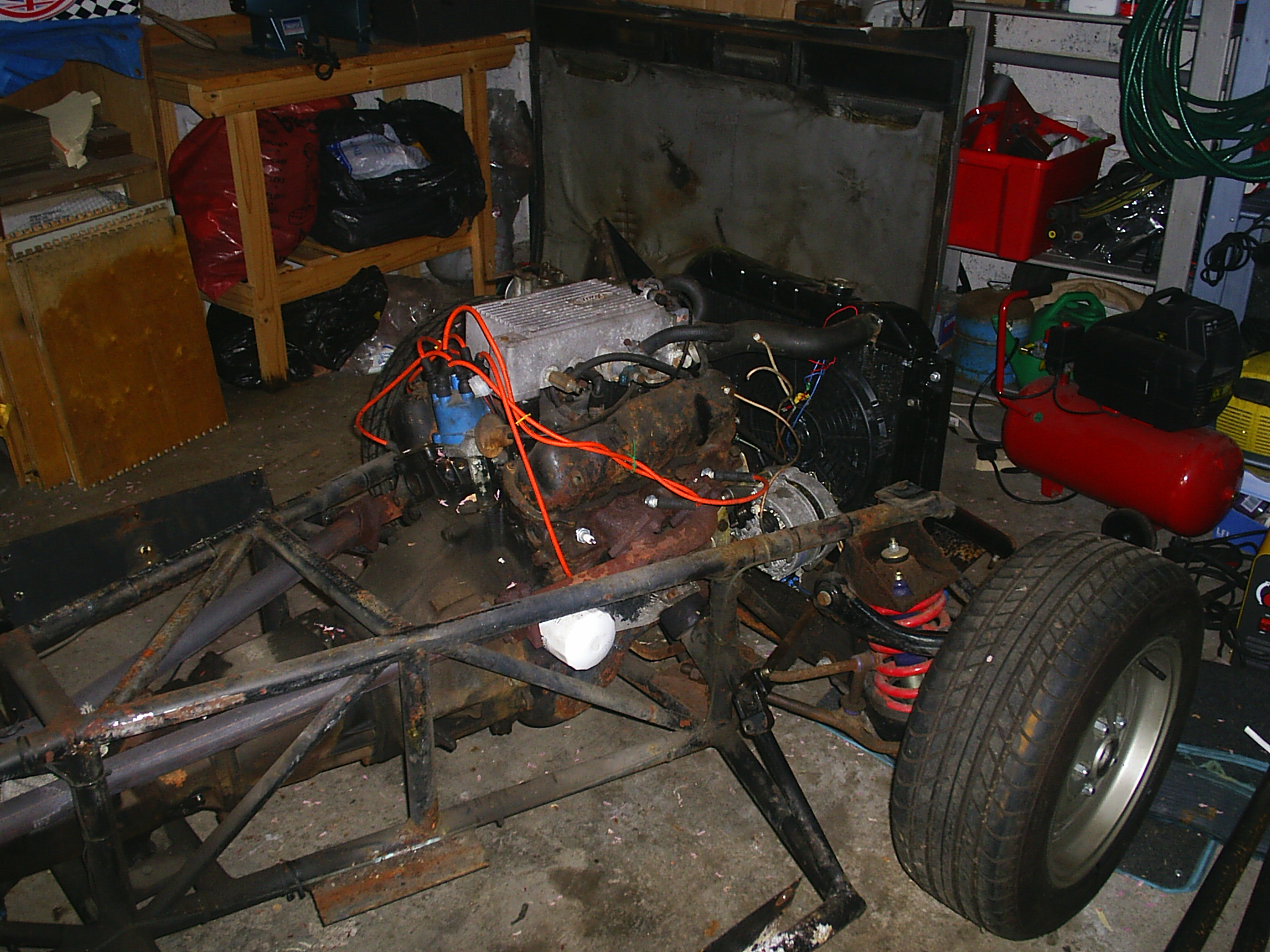
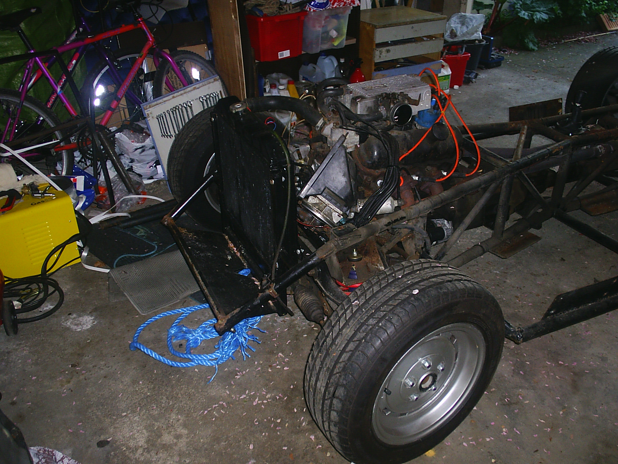
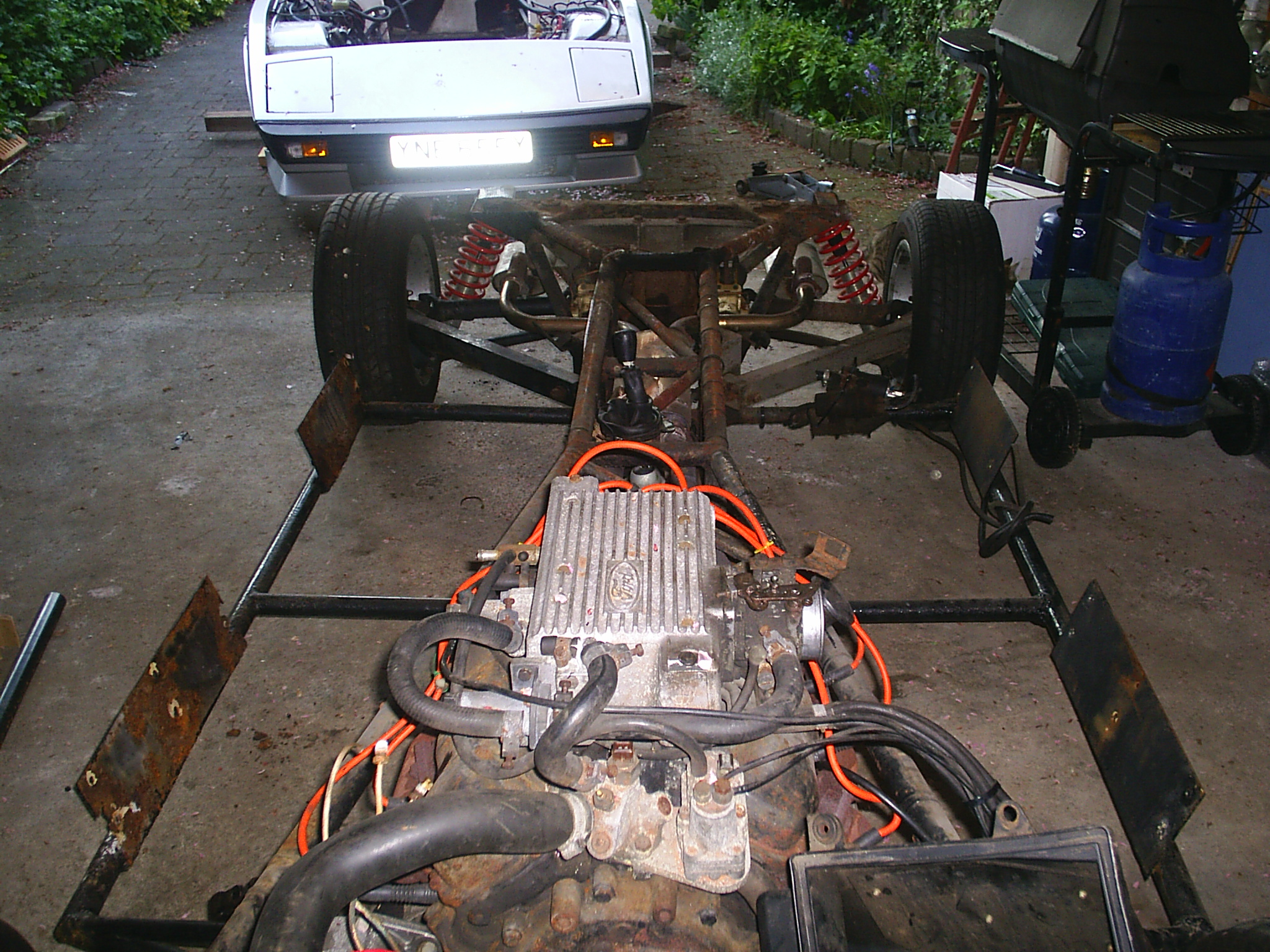
I had a 5 speed gearbox installed in mine and it went in as a straight replacement except that the gearlever was a few millimetres further back and the output for the speedo had a different fitting.
Not a naked photo but shows the gearlever position

You can see that I carved a bit of fibreglass out at the rear and bent the lever a bit more. Hope that helps
Not a naked photo but shows the gearlever position
You can see that I carved a bit of fibreglass out at the rear and bent the lever a bit more. Hope that helps
Ta, I have a 5 speed type 9 in there at the moment, but I have something more exotic in mind. its bolt compatible with the T9 ( although I need a different input shaft as the one i have was destined for a v8)
The box has 6 speeds and a leaver that only goes backwards and forwards :smile:
its just a bit taller than the T9 so may need a couple of subtle chassis mods. I dont have access to the car at the moment but the pics are proving useful.
The box has 6 speeds and a leaver that only goes backwards and forwards :smile:
its just a bit taller than the T9 so may need a couple of subtle chassis mods. I dont have access to the car at the moment but the pics are proving useful.
 to get the engine out over the break, but when it does come out you're welcome to have a shufty around.


Graham said:
Chassis? What chassis?.
Yep that's an M 2500M I think. That pic was done like that to distract you from looking at the s t welding.
It never got much better, I recall seeing some Carb chassis at the factory, welding by Mr. Blobby!Yep that's an M 2500M I think. That pic was done like that to distract you from looking at the s
t welding.I asked the tour guide if they did any non-destructive testing of new chassis and he hopped from one foot to the other, coughed a bit, rolled his eyes a bit and said "Er...yeah...we...er... ultrasonic them."
Which is complete ballcocks: UT (ultrasonic testing) won't tell you quickly if the weld's any good, you'd need x-ray for that

Maybe they had an ultrasonic thickness gauge that they used to check the wall thickness of tube and plate, but using a true flaw detector to determine weld penetration etc. is a skilled craft - if there was a Level 3 UT tech. in there I'll eat my underwear: Peter wouldn't have paid the money

Wedg1e, the welds, tube diameter and wall thickness are too small for UT, especially in those days. In addition, the geometry of most welds is all wrong to get the sound in given that most are fillet type and not true full pen welds. Surface NDT would have been best option to quickly find cracking, pores, porosity and so on. Looking at the welds I've seen on some wedges, it's doubtful this was done!
Wedg1e, the welds, tube diameter and wall thickness are too small for UT, especially in those days. In addition, the geometry of most welds is all wrong to get the sound in given that most are fillet type and not true full pen welds. Surface NDT would have been best option to quickly find cracking, pores, porosity and so on. Looking at the welds I've seen on some wedges, it's doubtful this was done!
ETA: double post, dang I-phone...
ETA: double post, dang I-phone...
Edited by J.B.R. on Wednesday 5th January 20:53


J.B.R. said:
Wedg1e, the welds, tube diameter and wall thickness are too small for UT, especially in those days. In addition, the geometry of most welds is all wrong to get the sound in given that most are fillet type and not true full pen welds. Surface NDT would have been best option to quickly find cracking, pores, porosity and so on. Looking at the welds I've seen on some wedges, it's doubtful this was done!
Absolutely. Can't see them doing dye pen or MPI though, too slow and fiddly on a chassis. To be fair, I don't think there's a car assembly technique that DOES involve any NDT; certainly spot-welded monococques just rely on the welder being set up correctly - so on a tube chassis it's down to the integrity of the MIG-monkey You're right Wedg1e, I've never seen any chassis photos with evidence of mpi or dpi remnants on the welds.
On normal cars, NDT is more common than you may think e.g. Toyota carry out specialist UT on spot welds on the wings to inner wings on some models as this is a main strength area for the crash test. Jaguar used to x-ray the cross members on the xjs.
NDT mainly started in formula 1 following the senna crash attributed to poor welding on the steering column.
Gassing Station | Wedges | Top of Page | What's New | My Stuff