Very quicky quessi
Discussion


Question 1. (multiple choice)
Is the bore size (samco elbow) for the top main water port on the LS7:
a. 35mm
b. 32mm
c. don't use samco
Question 2. (multiple choice)
What Tank/side is feeding the fuel using the factory valve unit when at rest (no current):
a. The right side (off side in the UK)
b. The left side (near side in the UK)
c. No side at all cos its broken.
pass-mark is 100%

can't you tell I am bored!
Serious questions though...I want to order some stuff before 3pm
cheers
keith
Is the bore size (samco elbow) for the top main water port on the LS7:
a. 35mm
b. 32mm
c. don't use samco
Question 2. (multiple choice)
What Tank/side is feeding the fuel using the factory valve unit when at rest (no current):
a. The right side (off side in the UK)
b. The left side (near side in the UK)
c. No side at all cos its broken.
pass-mark is 100%
can't you tell I am bored!
Serious questions though...I want to order some stuff before 3pm
cheers
keith
Edited by 3Dee on Thursday 19th July 13:35
For the water outlets.... the water pump side is 28mm and the thermostat side is 32mm on my LS3. I'm not sure if these are the same on the LS7 or not.
As for the valve... I though you were using a bespoke fuel system? Or is it some kind of wacky hybrid you've pulled together with some garden hose & tin cans ;-)
As for the valve... I though you were using a bespoke fuel system? Or is it some kind of wacky hybrid you've pulled together with some garden hose & tin cans ;-)
UltimaCH said:
Good Lord, I hope not or we will have to suffer with another fuel system thread, when there are some good solutions around 
Yep...you do!Search Facility has been knackered on this site for Yonks, and the Site support folk don't seem to be giving a stuff, or they don't have the skills to fix it????????
I am just revising my options, and if I could throw away the factory valve system without too much additional work, then obviously I would...
Edited by 3Dee on Friday 20th July 11:42

I noticed the 'don't use Samco' comment on your original post. We have used DPH (Derby Performance Hose)and AP Performance store on eBay for all our silicon hoses and have never had an issue. Plenty of choice and much cheaper than Samco. In fact, if it wasn't for the label you really couldn't tell the difference.
Another vote for AP Performance Store for all things silicone hose / joiner related.
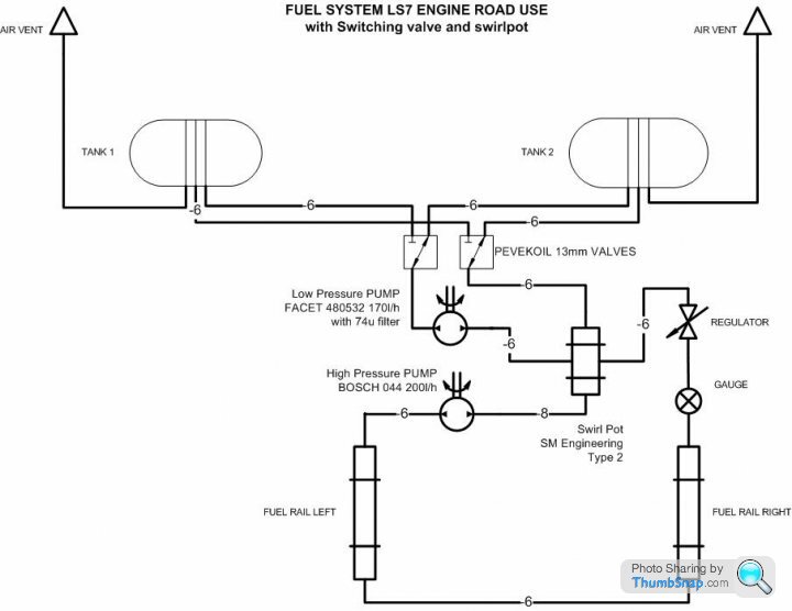
As for fuel systems, here's a photo of my setup... I've gone the simple route, with a changeover-less setup & swirl pot....
Both tanks are linked to each other via the bottom, forward-most (when viewed from the engine bay) fitting.
The bottom rear-most fitting of each tank outlets into filters and then individual LP pumps.
The LP pumps exit and feed directly into the swirl pot.
The swirl pot contains a HP pump, which feeds a pressure regulator.
The pressure regulator feeds the rails (which are non-return) and excess fuel is sent back from the reg to the swirl pot.
Excess fuel from the swirl pot goes back to each tank's top fitting.
Does this help / hinder?
Very nice and interesting installation Mark!
Jeez - massive swirlpot!
I presume you are relying on the fact that the system is constantly circulating fuel around both tanks, so even if one is initially fuller than another, they will equalise fairly quickly, thus little chance of one of the LP pumps running dry?
Nice one! - Wish I had thought of that one!
I know certain people might not like me bringing this up again, but the choice of methods of feeding from duel tanks seems to be quite diverse with many differing opinions and anecdotes, so I got confused and defaulted to the factory way.
I certainly would like to ditch the peetol valve method if i could, but many of the earlier suggestions revolved around having to replace the -6 fittings on some of the tank outlets to -10 or higher and frankly this is something that for me, I don't want to do.
Marks method seems simple enough and presumably retains the -6 fittings all round.
If I could be confident that by connecting the outlet of both tanks to a Y and then to my big LP pump to feed the (admittedly smaller) swirl tank, then back out the excess from the swirl pot to a single line to a T in the top returning fuel line to both sides without causing starvation or inadvertant overflowing of either tank, I would do it, but I don't have the experience to know what the outcome would be...
any comments?
You're right Keith, there's a lot of diverse methods of feeding from the twin tanks, I wanted as straight forwards a setup as possible, with both tanks used in parallel.
As you say, the link allows both tanks to self equalise (admitedly fairly slowly of course) and with each tank having it's own LP pump, they should keep the big swirl pot nicely topped up. Std fitting sizes have been retained, so no change to the tanks themselves.
I've retained both fuel level senders and calibrated them both to my digital dash, so I can see usuage side-to-side. The dash gives an alarm for each tank as they hit 10% registered volume (recognising that there's 7l in each tank that the sender doesn't "see" and also 7l in the swirl pot on top of that too) and the fuel pressure regulator has a display channel & alarm too. I should be pretty well setup for fuel monitoring.
Assuming you already have the requisite fittings on the swirl pot, there's no reason why you couldn't convert the LP side of your system to something similar, without major hassle.
If you want to have a poke around my setup, you're welcome to pop down the road and have a look.
I've just done this to my car, both tanks are joined by a balance pipe and return is center teed to both tanks,
I have also retained both senders to monitor usage from each tank, I have used about three full (both sides) tankfuls so far without any incident or hint overflow.
Much better than that pollack valve afair IMO.
I have also retained both senders to monitor usage from each tank, I have used about three full (both sides) tankfuls so far without any incident or hint overflow.
Much better than that pollack valve afair IMO.
Keith, I think this is the thread you are looking for?
The installation you mentioned with the Y from the tanks then feeding the LP pump is the set up I went for. My Holley rattler packed up the weekend coming back from Brooklands (just made it home!) might be too hot where it is, but it has lasted three of more years.
http://www.pistonheads.com/gassing/topic.asp?h=0&a...
Mark, a very neat set up there wish I thought of that but it would have meant moving a lot of stuff around the bay.
Graham

If I was starting my rebuild now, and knowing what I now do, I would re-model the chassis to mount a single tank behind the seats protected by a new firewall. I would mount the high pressure pump inside the tank in a small sump c/w filter (accessed though the top of the tank which would wrap round the front of the engine).
Filling would be via the standard filler points. The fuel regulator would be post the fuel rail and a single return to the tank.
The space in the side pods that this would free up would be used for the dry sump tank and allow more airflow past the headers to keep the under clip temperatures down.
These changes would require a considerable amount of design work on the chassis and a new tank but I think it would be worth it and solve a lot of issues.
This is my own opinion and uses ideas that are not all my own. I can understand why the Factory would not want to go down this route as it would involve considerable costs to design and tool up to make a new chassis. Also, a Factory set-up works in most cases so if it ain't broke don't fix it. However, even Morgan make changes over time and eventually Ultima will re-model the GTR/Can-Am and I would be surprised if this did not figure for very many good reasons.
Paul


Gassing Station | Ultima | Top of Page | What's New | My Stuff