Belt alignment
Discussion


I am placing a trigger wheel between my balancer and front pulley. This means that the front pulley is moving forward by @3.5mm.
Is it possible to space the pulley on the front of the alternator using a shim under the it?
Then I have to move the aircon compressor forward the same amount. I don't think that the pulley can be shimmed because of the electric clutch so the only other way is to mod the mounting bracket it seems.
Has anybody done this or have any suggestions as to how to align belts?
MarkWebb said:
I am placing a trigger wheel between my balancer and front pulley. This means that the front pulley is moving forward by @3.5mm.
Is it possible to space the pulley on the front of the alternator using a shim under the it?
Then I have to move the aircon compressor forward the same amount. I don't think that the pulley can be shimmed because of the electric clutch so the only other way is to mod the mounting bracket it seems.
Has anybody done this or have any suggestions as to how to align belts?
Is it not possible to modify the triggerwheel, so that you can mount it on the 3 tapped holes on the facing of the damper? (I have the SBC in mind, don't know if the damper on yours has holes on the damper) This way everything can stay in the same place. I'm planning to do this on my engine.Is it possible to space the pulley on the front of the alternator using a shim under the it?
Then I have to move the aircon compressor forward the same amount. I don't think that the pulley can be shimmed because of the electric clutch so the only other way is to mod the mounting bracket it seems.
Has anybody done this or have any suggestions as to how to align belts?
If its possible just make sure enough of the outer hub face remains exposed when fully pressed onto the crank otherwise the bolt will be tight but not clamping the damper hub. If this is a potential problem just have someone turn you a top-hat or recessed type washer for the damper retaining bolt.....you will get the same clamping force as standard.
Good luck.
Good luck.
Grip from the inside or turn a mandrel, you only really need to get the face to run true so it clamps the timing gear square. The lead-in for the seal will stand being slightly off so long as its smooth.... balance forces so close to the centreline will be unaffected.
I have done LS dampers, also bonded and including turning additional belt grooves in a similar fashion... they work out fine.
Lastly if your damper hub is very hard (test with a file), just square up the damper in the chuck then clamp a 4 inch grinder to the toolpost and gently grind off the few mm with the lathe turning very slowly. Polish the lead in by hand in the running lathe.
This also works very well and you can work to a suprisingly accurate standard so long as the ginder is firmly fixed.
Have fun
Edited by 738 driver on Friday 26th November 10:06
What trigger wheel do you have. When I did mine the first time I used a pressed steel Ford 36-1 toothed wheel. I placed this on the back of the damper, secured with small button head bolts (x6), so the teeth faced the timing cover. To gain clearance I had to cut the teeth down by 3mm.
I have since moved away from this approach and while I had the engine out over last winter I got 36-1 holes machined into the back of my flywheel and made up a new sensor bracket. I then had to get the flywheel balanced which was the downside, but it does make for a much more robust solution.
You can easily get different trigger wheels these days, some on ebay and most by triggerwheels.com. These are quite thin and look a bit like bike gears so would probably be easier to fit to the back of the damper. Putting more weight on the front and having to respace everything is not easy or a good idea.
I have pics of both of my methods if that helps.
Thin ford 36-1 wheel on my SBC:
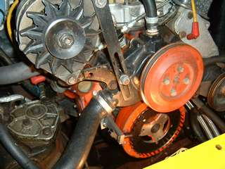
I turned a small shoulder on the damper (the solid part, not the moving part).
Bigger photo:
http://www.mez.co.uk/dcam/DSCF1247.JPG
I turned a small shoulder on the damper (the solid part, not the moving part).
Bigger photo:
http://www.mez.co.uk/dcam/DSCF1247.JPG
Gassing Station | Ultima | Top of Page | What's New | My Stuff