Quickest way to learn basic electronic diagnosis?
Discussion


I've a used watch timing machine that will no longer switch on. They're close to two grand new, but I got mine for less that £500, and the only quote I can find for repair is ~£300. For that money, assuming it's not a problem with a computer chip, surely I could get a decent electronic PCB repair for dummies book, decent soldering iron and replacement duff resistor/capacitor/whatever, no?
If you can get a schematic for it then there's no reason why you couldn't work out what's wrong and pin it down to a component using expected figures and a multimeter.. find your OC or short and solder in whatever has died.
Just practice your soldering a bit first..
(RAF electronics and radar geek)
Just practice your soldering a bit first..
(RAF electronics and radar geek)
paulrhodes said:
If you can get a schematic for it...
Yeah, right 
glazbagun said:
used watch timing machine
I don't know what one of those is, so my comments are general; but I doubt a book will be much help. For one thing, "won't switch on" suggests a computerised device in which the fault is either something obvious like a duff connection, bad contact, broken wire/track or the like which you can find by inspection and beeping it out with the multimeter without reading anything, or something abstruse which is beyond the scope of such a book and may well not be fixable anyway...
For another, learning fault finding is harder than learning "hobby electronics" as in how to build radios and flashing LED thingies... not only do you have to learn how circuits more complex than hobby book ones and using techniques alien to the hobby book world work, you then have to learn how they don't work too
Pigeon said:
paulrhodes said:
If you can get a schematic for it...
Yeah, right glazbagun said:
used watch timing machine
I don't know what one of those is, so my comments are general; but I doubt a book will be much help. For one thing, "won't switch on" suggests a computerised device in which the fault is either something obvious like a duff connection, bad contact, broken wire/track or the like which you can find by inspection and beeping it out with the multimeter without reading anything, or something abstruse which is beyond the scope of such a book and may well not be fixable anyway...
For another, learning fault finding is harder than learning "hobby electronics" as in how to build radios and flashing LED thingies... not only do you have to learn how circuits more complex than hobby book ones and using techniques alien to the hobby book world work, you then have to learn how they don't work too
1) Go round all the 'chips' identify them on the internet. Find the power and ground pins and check they all have the right power across them.
2) Go round all the transistors, check they are all forward biased when the thing is switched on.
Just those two things in my experience sorts out at least a third to a half of all problems.


Pigeon said:
I don't know what one of those is, so my comments are general; but I doubt a book will be much help.
For one thing, "won't switch on" suggests a computerised device in which the fault is either something obvious like a duff connection, bad contact, broken wire/track or the like which you can find by inspection and beeping it out with the multimeter without reading anything, or something abstruse which is beyond the scope of such a book and may well not be fixable anyway...
For another, learning fault finding is harder than learning "hobby electronics" as in how to build radios and flashing LED thingies... not only do you have to learn how circuits more complex than hobby book ones and using techniques alien to the hobby book world work, you then have to learn how they don't work too
You laugh but aside from the fact that you don't even know what one is... someone manufactures it and assuming the company exists may well be able to provide something for it.For one thing, "won't switch on" suggests a computerised device in which the fault is either something obvious like a duff connection, bad contact, broken wire/track or the like which you can find by inspection and beeping it out with the multimeter without reading anything, or something abstruse which is beyond the scope of such a book and may well not be fixable anyway...
For another, learning fault finding is harder than learning "hobby electronics" as in how to build radios and flashing LED thingies... not only do you have to learn how circuits more complex than hobby book ones and using techniques alien to the hobby book world work, you then have to learn how they don't work too
Its certainly far easier to diagnose a fault if you know if/where any test points are and what to expect from them.
Is if for watches. If so, they work by timing giving the + or - of watch period of a day / week.
and need a good FIXED timing source. Usually a crystal oven.
Is it for digital watches as well as analogue ones? Is the display LCD or LED?
Does it have a separate adapter or does the unit plug straight into the mains?
Is there NO display at all? Any power light? or anything?
Is it a modern or old bit of equipment.
Yeah, it's a digital timing machine for mechanical watches from somewhere ~89-92. It compares the sounds from a microphone of the watch ticking with a quartz time source and produces a digital readout from which to rate/diagnose escapement problems. Replaced the power source first & crossed my fingers, but no joy. The thing is dead to the world with the following exceptions-
Occasionally, switching it on, the speaker makes that initial "thunk" that speakers make when you turn things on, but not always.
And in all cases when switched "on", pressing the "freeze display" button causes the yellow correct LED to come on. Not sure what to make of that.
I'll grab a multimeter this weekend in case it's something like a broken "on" switch.
Edited by glazbagun on Wednesday 9th February 12:44
Sorry to drag this up from the dead, but my recent stupidity has given me an idea-
I recently connected a cheap Chinese timing machine to a multi-adapter, and didn't read the polarity right, causing much smoke and smell for a split second. It got me thinking about my old ElecEng lectures (yes, really ) and polarity protection....
If I've simply reversed polarity on these things at some point, will there be any visible damage to a diode/whatever that will simply require replacement? The thing that stands out in particular is in this first photograph- above the letters TP12, there is a component which seems to be connected to the board in a different manner to the other components:
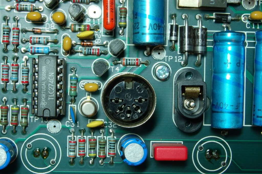
High rez: https://rapidshare.com/files/459355180/DSC_0077.JP...
The Chinese one I cooked looks like so:

High rez: https://rapidshare.com/files/459355179/DSC_0071.JP...
I recently connected a cheap Chinese timing machine to a multi-adapter, and didn't read the polarity right, causing much smoke and smell for a split second. It got me thinking about my old ElecEng lectures (yes, really
) and polarity protection....If I've simply reversed polarity on these things at some point, will there be any visible damage to a diode/whatever that will simply require replacement? The thing that stands out in particular is in this first photograph- above the letters TP12, there is a component which seems to be connected to the board in a different manner to the other components:
High rez: https://rapidshare.com/files/459355180/DSC_0077.JP...
The Chinese one I cooked looks like so:
High rez: https://rapidshare.com/files/459355179/DSC_0071.JP...
glazbagun said:
Sorry to drag this up from the dead, but my recent stupidity has given me an idea-
I recently connected a cheap Chinese timing machine to a multi-adapter, and didn't read the polarity right, causing much smoke and smell for a split second. It got me thinking about my old ElecEng lectures (yes, really ) and polarity protection....
If I've simply reversed polarity on these things at some point, will there be any visible damage to a diode/whatever that will simply require replacement? The thing that stands out in particular is in this first photograph- above the letters TP12, there is a component which seems to be connected to the board in a different manner to the other components:
High rez: https://rapidshare.com/files/459355180/DSC_0077.JP...
The Chinese one I cooked looks like so:
High rez: https://rapidshare.com/files/459355179/DSC_0071.JP...
The solder on that 1N1004 diode (just above TP12 notation) looks quite dry?I recently connected a cheap Chinese timing machine to a multi-adapter, and didn't read the polarity right, causing much smoke and smell for a split second. It got me thinking about my old ElecEng lectures (yes, really
) and polarity protection....If I've simply reversed polarity on these things at some point, will there be any visible damage to a diode/whatever that will simply require replacement? The thing that stands out in particular is in this first photograph- above the letters TP12, there is a component which seems to be connected to the board in a different manner to the other components:
High rez: https://rapidshare.com/files/459355180/DSC_0077.JP...
The Chinese one I cooked looks like so:
High rez: https://rapidshare.com/files/459355179/DSC_0071.JP...
Gassing Station | Homes, Gardens and DIY | Top of Page | What's New | My Stuff