What are these gears doing?
Discussion


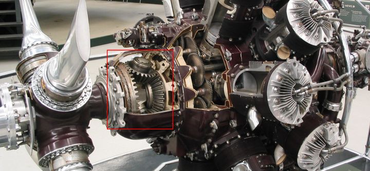
This is the fabulous Bristol Hercules sleeve valve engine.
How do the gears I have highlighted in red work? It seems to me the large inlet gear will drive the smaller gear say twice for each inlet shaft rotation. Then those smaller gears will drive the larger outlet once for every two smaller gear rotations. So all in all no gearing up or down as far as I can see. So what is the point of those gears?
How do the gears I have highlighted in red work? It seems to me the large inlet gear will drive the smaller gear say twice for each inlet shaft rotation. Then those smaller gears will drive the larger outlet once for every two smaller gear rotations. So all in all no gearing up or down as far as I can see. So what is the point of those gears?
Hard to be completely sure without seeing what is fixed to what, but I'd assume it's working in a similar way to how a planetary gear might be used and the spider is connected to either input or output and it's used as either a permanent or selectable way to have the prop speed different for the crank speed?
I think the propeller pitch adjustment is done further forward, in the hub. The gearing behind it is likely the propeller speed reduction unit (PSRU). essentially a gearbox to allow the engine to drive the propeller at the most efficient speed.
It can be made to rotate the propeller the other way for counter rotating props on multi engine aircraft. Although British multi engine WW2 aircraft like the Mosquito and even the Lancaster didn’t bother with such niceties. All their propellers rotated clockwise as seen from behind.
It can be made to rotate the propeller the other way for counter rotating props on multi engine aircraft. Although British multi engine WW2 aircraft like the Mosquito and even the Lancaster didn’t bother with such niceties. All their propellers rotated clockwise as seen from behind.
Fair enough chaps! I did say it was an uninformed guess!
An old colleague of mine would have known instantly. He once asked me to think about rotary aero engines and postulate how the ignition HT and other functions would be arranged with the cylinder block spinning around a stationary crankshaft. Unfortunately he died before he could tell me the answer. Wikipedia didn't exist then but fortunately it does now!
An old colleague of mine would have known instantly. He once asked me to think about rotary aero engines and postulate how the ignition HT and other functions would be arranged with the cylinder block spinning around a stationary crankshaft. Unfortunately he died before he could tell me the answer. Wikipedia didn't exist then but fortunately it does now!
hidetheelephants said:
It's a reduction gear, it reduces the RPM at the propellor so the tips don't go supersonic. The ring gear on the left is fixed, the ring gear on the right is attached to the crankshaft, the spider is attached to the propellor.
Very simple explanation thanks. I assumed the left gear was attached to the prop. Why is the left gear needed at all? It just adds weight right?Edited by hidetheelephants on Monday 4th August 15:50
Would one rev of the engine give about 1/4 turn of the prop with this arrangement?
LimaDelta said:
Its an epicyclic reduction gear. The ratio is 0.44:1 according to Wikipedia. It just simply steps down the engine output to an appropriate prop speed, allowing both to be run at more efficient speeds. Nothing to do with varying the blade pitch.
Aha that answers one of my questions then. So the prop turns 0.44 of a turn for one turn of the engine.Why so many cogs? Surely one on the crankshaft and one on the prop could do the same thing?
hidetheelephants said:
Rotary engines are wild, practically witchcraft. It's remarkable they work at all, never mind as well as they did.
The interesting thing to me about the Hercules is the designer went for sleeve valves as he realised the poppet valve gear would be too complicated in a double bank rotary engine.Aircraft design developed massively in the first few decades of the 20thC but engine tech did similarly. The guys back then were geniuses.
Scarletpimpofnel said:
Aircraft design developed massively in the first few decades of the 20thC but engine tech did similarly. The guys back then were geniuses.
They were indeed - and did with slide rules not CAD.Schneider Trophy and all that - https://www.amazon.co.uk/Secret-Horsepower-Race-We...
Scarletpimpofnel said:
LimaDelta said:
Its an epicyclic reduction gear. The ratio is 0.44:1 according to Wikipedia. It just simply steps down the engine output to an appropriate prop speed, allowing both to be run at more efficient speeds. Nothing to do with varying the blade pitch.
Aha that answers one of my questions then. So the prop turns 0.44 of a turn for one turn of the engine.Why so many cogs? Surely one on the crankshaft and one on the prop could do the same thing?
hidetheelephants said:
Scarletpimpofnel said:
LimaDelta said:
Its an epicyclic reduction gear. The ratio is 0.44:1 according to Wikipedia. It just simply steps down the engine output to an appropriate prop speed, allowing both to be run at more efficient speeds. Nothing to do with varying the blade pitch.
Aha that answers one of my questions then. So the prop turns 0.44 of a turn for one turn of the engine.Why so many cogs? Surely one on the crankshaft and one on the prop could do the same thing?
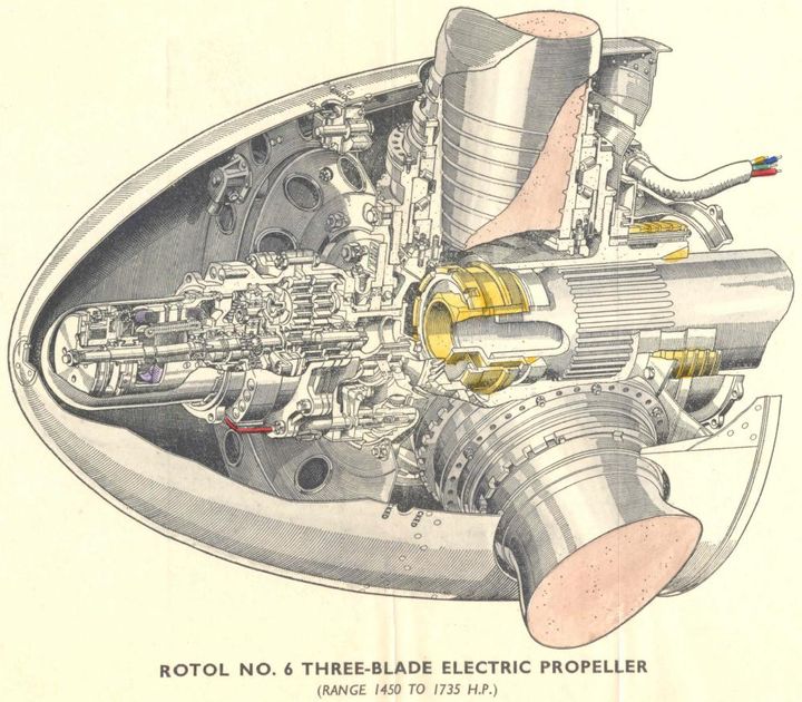
Prop blade pitch change was done by an electrically driven mechanism in the "bulb" that protrudes out of the front of the propeller hub. The Bristol engines used Rotol props which were based on a license built version of the Curtiss Electric propeller.
The Hamilton propellers used oil pressure to change the pitch hydraulically, and the German engines used a separate electric motor underneath the engine block to change the pitch via an epicyclic gear on the back of the propeller. All very clever.
The Hamilton propellers used oil pressure to change the pitch hydraulically, and the German engines used a separate electric motor underneath the engine block to change the pitch via an epicyclic gear on the back of the propeller. All very clever.
hidetheelephants said:
Scarletpimpofnel said:
LimaDelta said:
Its an epicyclic reduction gear. The ratio is 0.44:1 according to Wikipedia. It just simply steps down the engine output to an appropriate prop speed, allowing both to be run at more efficient speeds. Nothing to do with varying the blade pitch.
Aha that answers one of my questions then. So the prop turns 0.44 of a turn for one turn of the engine.Why so many cogs? Surely one on the crankshaft and one on the prop could do the same thing?
LimaDelta said:
You need to remember that the propellor is generating a huge amount of forward thrust, pulling the engine, and therefore the aircraft along in the air. The gearbox is also acting as a kind of thrust bearing, otherwise the propellor shaft would soon part company from the engine output with a straight cut traditional gearset (or you would need a traditional thrust bearing).
Interesting. So using this gear design is a trade between making extra gears (expensive/time consuming/specialist) and adding a thrust bearing and heavier gearbox casting for strength (heavier). Hercules went for the former, Merlin for the latter.hidetheelephants said:
There's no right answer, just a set of compromises; a simple gear train, especially with straight cut gears, is cheaper to make than the epicyclic on the Bristol, which as well as having more components the gears are bevel gears which are more expensive to make.
Yep agreed. I am thinking of the designers in wartime Britain making these decisions with limited time and testing whilst in a race with the enemy to maximise power and minimise weight...Simpo Two said:
They were indeed - and did with slide rules not CAD.
Schneider Trophy and all that - https://www.amazon.co.uk/Secret-Horsepower-Race-We...
I looked that book up... looks fascinating... definitely on my buy list. TY.Schneider Trophy and all that - https://www.amazon.co.uk/Secret-Horsepower-Race-We...
The last book I bought along these lines was (I think) called Slide Rule by Neville Shute. A cracking read.
Gassing Station | Science! | Top of Page | What's New | My Stuff