Can I wire with a negative switch to simply the fusebox?
Discussion


I would normally just wire a relay as follows (although I've never added a diode before).
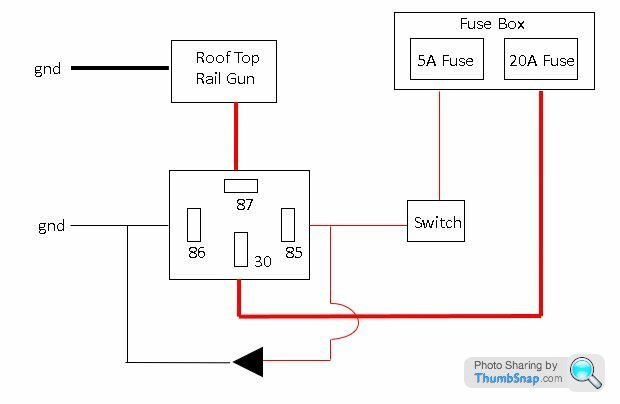
The above is fine, but when wiring a whole car, the number of fuses will soon rack up, and the complexity of the wiring behind the dash and at the fuse box may turn into a bit of a rats nest.
I was wondering whether the following proposal is acceptable?

By switching the ground wire, this switch wire wont need to be fused.
This means I can use a smaller fuse box and have less wiring going to it.
It also means that behind the dash gets a bit simpler as I can just have one wire going to each switch, then string them all together and ground.
It's not game changing, but seems a little more efficient to me.
This may be a normal approach, but I couldn't find anyone promoting it.
- Can anyone see a problem with my negative switches relay proposal?
- Would you bother with the diode. I have no plans for any digitally controlled switches.
Thanks
The above is fine, but when wiring a whole car, the number of fuses will soon rack up, and the complexity of the wiring behind the dash and at the fuse box may turn into a bit of a rats nest.
I was wondering whether the following proposal is acceptable?
By switching the ground wire, this switch wire wont need to be fused.
This means I can use a smaller fuse box and have less wiring going to it.
It also means that behind the dash gets a bit simpler as I can just have one wire going to each switch, then string them all together and ground.
It's not game changing, but seems a little more efficient to me.
This may be a normal approach, but I couldn't find anyone promoting it.
- Can anyone see a problem with my negative switches relay proposal?
- Would you bother with the diode. I have no plans for any digitally controlled switches.
Thanks
voram said:
All well and good - but what, then, is the point of the relay? You might as well just use a 20amp switch.
There are a few benefits.I can use any switches I like.
A lot less heavy gauge wiring needed as the relays are close to the fusebox by design.
Less voltage drop with shorter heavy gauge wires.
I'd rather run skinny trigger wires everywhere so I think the relays are worth having.
voram said:
Don't forget you'll have a 20 amp fuse on that "skinny trigger wire" - so if you get a fault on that circuit you might set fire to the vehicle before the fuse blows. Ouch.
I don't see how?Where I use the ground trigger wire to switch, any shorting of this wire would require the electrons to flow through the 80ohms coil of the relay.
At most you'll get less than 0.2 amps.
Don't forget, when the switch is closed, this is exactly the same as shorting the wire.
A fault on this wire would just mean the relay is alway energised.
This may be considered another perk. I'd rather have the headlights stuck on rather than blow a fuse if I develop a fault on my trigger wire.
I was very careful in the diagram to show large gauge wires where a short would need to handle more than the 20 amp rating.
ColourRestorer said:
At the risk of being pedantic, the triangle on your diagram which I presume is meant to represent a freewheel diode, is drawn back to front:
The cathode should be connected to the more positive side of the relay coil.
Not pedantic at all.The cathode should be connected to the more positive side of the relay coil.
I copied the direction from the diagram of a relay with a built in diode I found from google.
The mistake I then went on to make was wiring the positive to 85 instead of 86.
If I'm adding my own diode this wont matter, but I may as well do it correctly so if a diode relay ever gets fitted it wont blow the diode.
Does anyone have advice if the diode is really necessary for normal switches?
Updated diagram below.

The danger remains that skinny wire on a 20 amp circuit. If a fault arises it can heat up and set fire to stuff.
I mean, at the simplest, you could put a separate inline fuse of lower amperage in the skinny switching wire. Dead simple, but since you've already explained where the components are located it would, for practical purposes, be exactly the same as that first diagram with the two fuses.
I mean, at the simplest, you could put a separate inline fuse of lower amperage in the skinny switching wire. Dead simple, but since you've already explained where the components are located it would, for practical purposes, be exactly the same as that first diagram with the two fuses.
voram said:
The danger remains that skinny wire on a 20 amp circuit. If a fault arises it can heat up and set fire to stuff.
I mean, at the simplest, you could put a separate inline fuse of lower amperage in the skinny switching wire. Dead simple, but since you've already explained where the components are located it would, for practical purposes, be exactly the same as that first diagram with the two fuses.
I still don't understand this comment.I mean, at the simplest, you could put a separate inline fuse of lower amperage in the skinny switching wire. Dead simple, but since you've already explained where the components are located it would, for practical purposes, be exactly the same as that first diagram with the two fuses.
The skinny wire is already grounded (when the switch is closed).
No fault to the wiring could draw any more current than this. Grounding it again is exactly the same as closing the switch.
Unless you're suggesting the coil in the relay could somehow short and loose it's high resistance, but is that really a risk worth mitigating? It wouldn't surprise me if this has never happened.
Or maybe a positive wire somehow makes contact with a skinny ground wire, but a fuse wouldn't help you here anyway.
Here is a typical fault location which I think explains the problem better.
It wouldn't melt the skinny wire and the electrons have to pass through the coil to make a circuit. Or am I missing something?

Edited by montyjohn on Wednesday 11th August 16:38
Conventionally you'd want to fuse the output from the relay. This means that when you upgrade to a dual rail gun setup, they can be fused independently but powered through the same relay. That's a reason to put the fuse box and relay close together so that you don't have a long unprotected live cable. You might be sure that one is enough today, but who knows how you'll feel next year?
gazza285 said:
Why not just use a three pin relay?
I had a quick search for three pin relays and the only ones I can find are indicator flasher relays.If make/break three pin relays do exist they appear to be hard to find, suggesting they are probably expensive.
I think I'll stick with 4 pin and add a couple of inches of wire.
spikeyhead said:
It's rare for the insulation to break down on them, reducing the 80 ohm resistance, but I've seen it happen more than once
I'm surprised this happens. Is the consensus to leave the wiring as per the first diagram then. If the relays can and do fail in this way this is more than enough reason to keep the trigger wire fused.GreenV8S said:
when you upgrade to a dual rail gun setup
Are you crazy?Who need two rail guns? I'm not planning on invading a small country. Monaco is quite a nice country however.
On a serious note, my fuse box (already purchased) as one positive in, and multiple fused positive outs so it would be tricky to use it as you suggest. I would need a fuse box that has an input for every fused output so if I do decide to add another rail gun I'll either need to beef up the wires and add a bigger fuse, or just add a second relay and wiring running from the same trigger wire.
Of course a switched earth can be used for activating a relay
There will be no reduction in the length of cable used compared with a switched supply, when switching earth, obviously the other end of the relay coil needs a supply wiring to it
When switching a supply, obviously the other end of the relay coil needs an earth wiring to it. Earth points are easily found, supplies need to be run
There's a big downside to running a switched earth to activate a relay although some manufacturers do use this method
For example
Earth switching is used to operate a relay that will supply a starter motor solenoid, some time in the future the switched earth shorts to the chassis (earth) of the vehicle and the starter motor runs until disintegrating
If a fused switched positive used to operate a relay that will supply a starter motor solenoid shorts to the chassis (earth) of the vehicle the fuse will blow
Penelope Stopit said:
Of course a switched earth can be used for activating a relay
There's a big downside to running a switched earth to activate a relay although some manufacturers do use this method
Haha, I hadn't thought of this.There's a big downside to running a switched earth to activate a relay although some manufacturers do use this method
As it happens, I decided to go down the switched live route and just accept a large number of fuses.
montyjohn said:
Penelope Stopit said:
Of course a switched earth can be used for activating a relay
There's a big downside to running a switched earth to activate a relay although some manufacturers do use this method
Haha, I hadn't thought of this.There's a big downside to running a switched earth to activate a relay although some manufacturers do use this method
As it happens, I decided to go down the switched live route and just accept a large number of fuses.
Gassing Station | Home Mechanics | Top of Page | What's New | My Stuff