Toylander Restoration
Discussion


I suppose this topic could go in Scale Models or Kit Cars but I thought I'd put it here.
This is my rather sad looking Jeep that my dad built around 1990 from the plans and parts by Real Life Toys as Toylander were back then. Needless to say many hours of fun were had in it. Later it became my first foray into car modifications, although as to be expected with a ten year old's skills and funds, many were of questionable quality (yes those front spotlights on the bumper are baked bean tins).
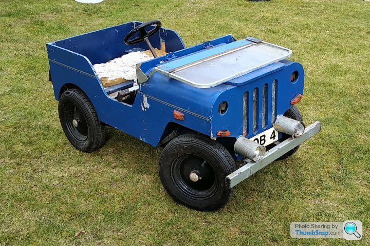
Eventually I attempted to fit a lawnmower engine, which involved butchering the sprocket in the rear wheel. As I was pretty much too big to fit in it by then, it was pushed to the back of the garage and left there.
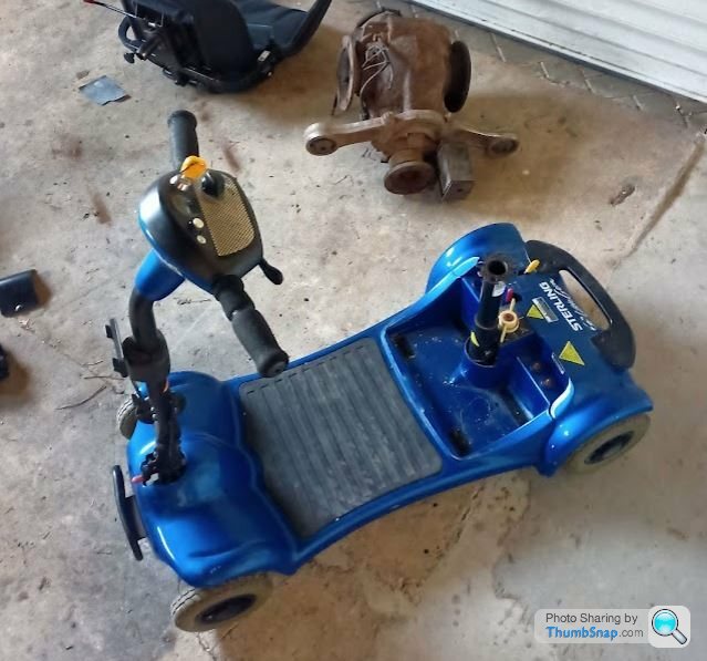
With a one year old I decided it was time to begin getting it ready for him; hopefully I should be able to get it done within the next three years. I bought this scooter for £156 delivered, being sold for spares because the fairing was cracked and the seat loose. All electrics work and the batteries appear to be decent, certainly good enough for the build and testing. Rather oddly this scooter has twin motors rather than the usual single motor, transaxle and differential set up.
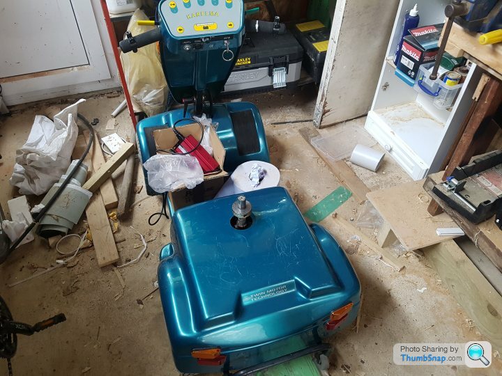
Today I got the motors out the scooter and trial positioned one motor where the origninal motor was. I always remember the Jeep struggling a bit with more than one person on board and just a single motor so hopefully the upgrade to twin motors will improve things.
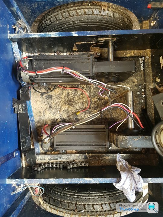
The shaft is rather too long for the job but I lack the skills/equipment to shorten the shaft and extend the keyway. So I just need to decide if the shaft needs an additional bearing at the end the furtherst from the gearbox. It did when it was on the scooter but then it needed to support the scooter wheel whereas it will now just have a sprocket on it. Obviously the next job is to make suitable mounts for the motors. I had also hoped to get new sprockets welded to both the rear wheels but none of the local engineering shops I spoke to have been interested in the work so I will be getting new rear wheels from Toylander in due course.
I'll try and keep this updated as I progress.
This is my rather sad looking Jeep that my dad built around 1990 from the plans and parts by Real Life Toys as Toylander were back then. Needless to say many hours of fun were had in it. Later it became my first foray into car modifications, although as to be expected with a ten year old's skills and funds, many were of questionable quality (yes those front spotlights on the bumper are baked bean tins).
Eventually I attempted to fit a lawnmower engine, which involved butchering the sprocket in the rear wheel. As I was pretty much too big to fit in it by then, it was pushed to the back of the garage and left there.
With a one year old I decided it was time to begin getting it ready for him; hopefully I should be able to get it done within the next three years. I bought this scooter for £156 delivered, being sold for spares because the fairing was cracked and the seat loose. All electrics work and the batteries appear to be decent, certainly good enough for the build and testing. Rather oddly this scooter has twin motors rather than the usual single motor, transaxle and differential set up.
Today I got the motors out the scooter and trial positioned one motor where the origninal motor was. I always remember the Jeep struggling a bit with more than one person on board and just a single motor so hopefully the upgrade to twin motors will improve things.
The shaft is rather too long for the job but I lack the skills/equipment to shorten the shaft and extend the keyway. So I just need to decide if the shaft needs an additional bearing at the end the furtherst from the gearbox. It did when it was on the scooter but then it needed to support the scooter wheel whereas it will now just have a sprocket on it. Obviously the next job is to make suitable mounts for the motors. I had also hoped to get new sprockets welded to both the rear wheels but none of the local engineering shops I spoke to have been interested in the work so I will be getting new rear wheels from Toylander in due course.
I'll try and keep this updated as I progress.
Edited by RECr on Saturday 3rd July 20:41

Looks like a good fun restoration job. I love the fact you modified it when you were a young lad.
I am starting to build a toylander style thing, but in metal for my two boys (4 & 2). I am not a welder or fabricator, or CAD person, so I thought I ought to try and gain some skills.
I have never used CAD before, so it took me a little time to make this;
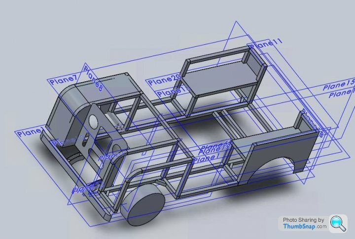
Obviously I found out about all the shortcuts like mirroring features after it was too late! My CAD level is most certainly basic, so all the straight lines of an early landrover suited me!
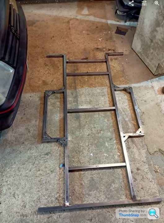
I finally started knocking up the chassis today.
As said, I am not a welder by trade either, so plenty of grinder action required, no, not that type!
I made a couple of fixture tables at work a couple of months ago, and it really is useful for this sort of job. Its basically a table that has 16mm through holes at 100mm pitch, and M12 thread holes at an offset 12mm pitch. This makes it very useful for welding simple (and complex, if you are good!) frames. You can use a combination of 16 / M12 holes to clamp and set the part.
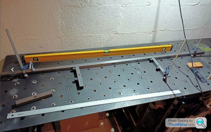
I need to get some nice squares lasered and fabbed up so that I can progress with the uprights and ensure it doesn't all end up completely on the piss. Partially pissed is fine.
Frame is 1.6mm thickness and will have further adhoc bracing than what is shown in the CAD.
I have a scooter, albeit with fairly knackered batteries. It seems to work ok when I hooked up some average batteries, although I am not sure it is going to cope too well with hills if I gear it up with the bigger tyres.
It is a single motor with a diff, but most definitely not the one shown in the photo.
I have yet to decide whether to use 0.9mm Alu rivetted to the chassis for the "bodywork" or whether to use 0.9mm mild steel and weld it...
Target weight is less than 50KG for the project, but no special attention really to achieve that. Whoops!
I am starting to build a toylander style thing, but in metal for my two boys (4 & 2). I am not a welder or fabricator, or CAD person, so I thought I ought to try and gain some skills.
I have never used CAD before, so it took me a little time to make this;
Obviously I found out about all the shortcuts like mirroring features after it was too late! My CAD level is most certainly basic, so all the straight lines of an early landrover suited me!
I finally started knocking up the chassis today.
As said, I am not a welder by trade either, so plenty of grinder action required, no, not that type!
I made a couple of fixture tables at work a couple of months ago, and it really is useful for this sort of job. Its basically a table that has 16mm through holes at 100mm pitch, and M12 thread holes at an offset 12mm pitch. This makes it very useful for welding simple (and complex, if you are good!) frames. You can use a combination of 16 / M12 holes to clamp and set the part.
I need to get some nice squares lasered and fabbed up so that I can progress with the uprights and ensure it doesn't all end up completely on the piss. Partially pissed is fine.
Frame is 1.6mm thickness and will have further adhoc bracing than what is shown in the CAD.
I have a scooter, albeit with fairly knackered batteries. It seems to work ok when I hooked up some average batteries, although I am not sure it is going to cope too well with hills if I gear it up with the bigger tyres.
It is a single motor with a diff, but most definitely not the one shown in the photo.
I have yet to decide whether to use 0.9mm Alu rivetted to the chassis for the "bodywork" or whether to use 0.9mm mild steel and weld it...
Target weight is less than 50KG for the project, but no special attention really to achieve that. Whoops!
Bookmarked. I’m currently putting the toylander’s big brother back together on my drive.
On a similar note one of my favourite ever mini off roaders was a 3/4 scale Series One Landrover featured in a copy of the first Landrover magazine I ever bought in about 1992. It was an absolutely perfect replica powered by a three cylinder Diesel engine from a compact tractor.
On a similar note one of my favourite ever mini off roaders was a 3/4 scale Series One Landrover featured in a copy of the first Landrover magazine I ever bought in about 1992. It was an absolutely perfect replica powered by a three cylinder Diesel engine from a compact tractor.
RECr I thought I should stop hijacking your thread so I made my own;
https://www.pistonheads.com/gassing/topic.asp?h=0&...
Have you made any progress with yours?
https://www.pistonheads.com/gassing/topic.asp?h=0&...
Have you made any progress with yours?
Lots of odd jobs on the house and full size car have meant i haven't spent as much time on this as I'd have liked. But I do now have two new rear wheels from Toylander, plus a pair of sprockets for the motors. Hopefully I will be able to get at least one motor fitted this weekend.
In the scooter the motors directly drove 11" dia wheels. The Toylander wheels are 15" overall diameter with an 18t sprocket. I have got 12t sprockets for the motors so the gearing will be slightly shorter than that on the scooter.
In the scooter the motors directly drove 11" dia wheels. The Toylander wheels are 15" overall diameter with an 18t sprocket. I have got 12t sprockets for the motors so the gearing will be slightly shorter than that on the scooter.
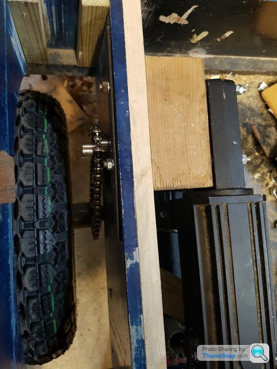
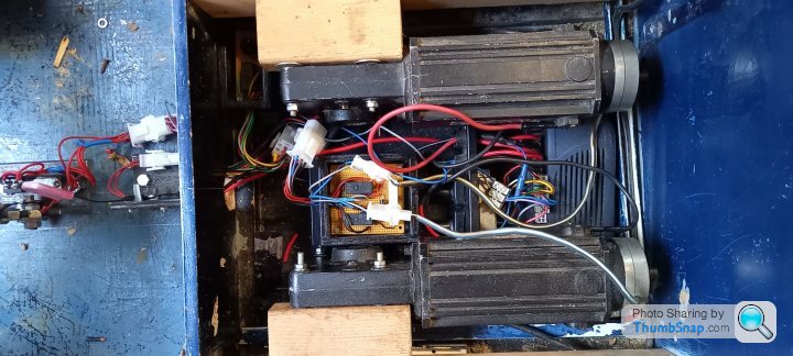
There was a little trial and error involved but I have now fitted the first motor. Originally the motor mount board flexed a little. To remedy this I added corner blocks to the joints and glued an additional board to double the thickness of the original.
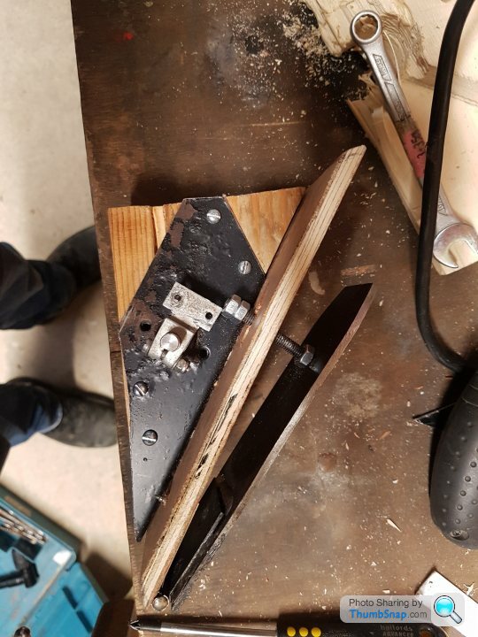
The lower mounting holes for the motor neatly lined up with the axle mounting holes so to get around this a piece of steel angle was bolted to the floor for the motor bolts to go through. This will have a piece of wood glued to the floor behind it to spread the load on the MDF floor. Excuse the messy slots.
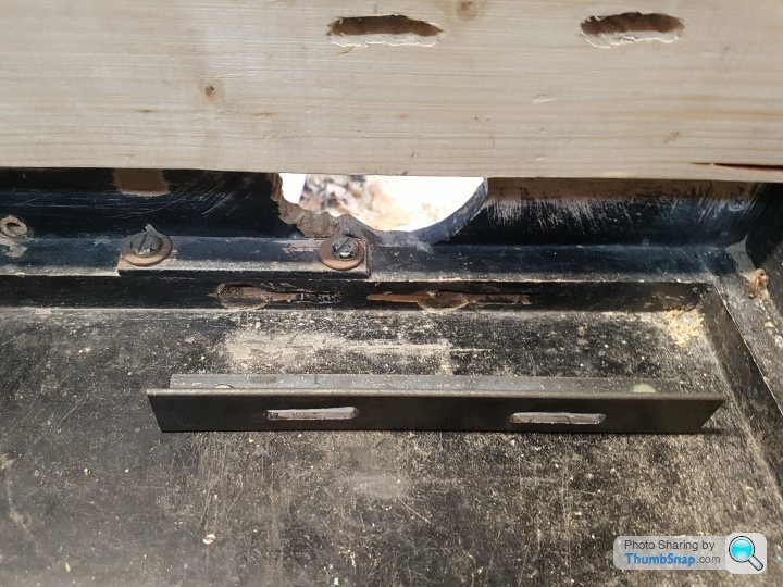
The motor could now be bolted in. The sprockets were bought from Technobots pre bored to suit the 20mm dia motor shaft. The grub screw on the sprocket engages in the existing keyway on the shaft.
I suspect I may need to add a tensioner to the chain as the centres of the sprockets on the motor and wheel don't seem to align exactly and there is therefore more slack in one side of the chain than the other. However I will see how it behaves on a test run.
It should now be a case of rinse and repeat for the other side.
The lower mounting holes for the motor neatly lined up with the axle mounting holes so to get around this a piece of steel angle was bolted to the floor for the motor bolts to go through. This will have a piece of wood glued to the floor behind it to spread the load on the MDF floor. Excuse the messy slots.
The motor could now be bolted in. The sprockets were bought from Technobots pre bored to suit the 20mm dia motor shaft. The grub screw on the sprocket engages in the existing keyway on the shaft.
I suspect I may need to add a tensioner to the chain as the centres of the sprockets on the motor and wheel don't seem to align exactly and there is therefore more slack in one side of the chain than the other. However I will see how it behaves on a test run.
It should now be a case of rinse and repeat for the other side.
Both motors now installed
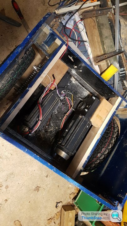
Batteries and speed control thrown in for testing
Much as I'd love to say it worked fine first time, the two wheels spun in opposite directions. The motor that was incorrect polarity was also very reluctant to turn. I got it back out and a brush is sticking in its holder. I'm now trying to free it off.
Unfortunately I couldn't find the exact brushes for the motor, however I managed to get some brushes the same size. I was then able to get them to fit to the brush springs.
I've done a brief test run. As there wasn't room to sit in the jeep with the batteries temporarily chucked in, it was done with the scooter controls from outside the jeep.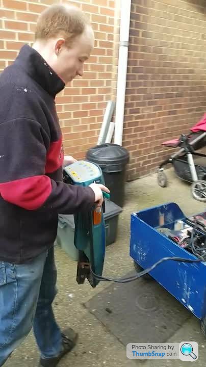
Like pretty much all scooters forward and reverse is controlled by a wig wag type control. I am going to try and adapt the wig wag to build an accelerator pedal box.
From reading the speed controller manual it looks like a reverse switch can be fitted to the low current side of the speed control.
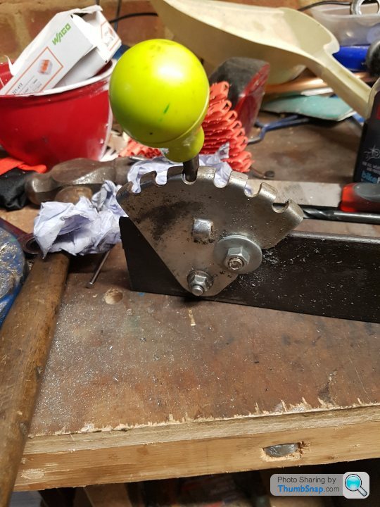
I also began to build a gear lever from a lawnmower height adjuster. I will be adding microswitches for the reverse and 4mph/8mph functions.
I've done a brief test run. As there wasn't room to sit in the jeep with the batteries temporarily chucked in, it was done with the scooter controls from outside the jeep.
Like pretty much all scooters forward and reverse is controlled by a wig wag type control. I am going to try and adapt the wig wag to build an accelerator pedal box.
From reading the speed controller manual it looks like a reverse switch can be fitted to the low current side of the speed control.
I also began to build a gear lever from a lawnmower height adjuster. I will be adding microswitches for the reverse and 4mph/8mph functions.
Edited by RECr on Sunday 30th January 17:35
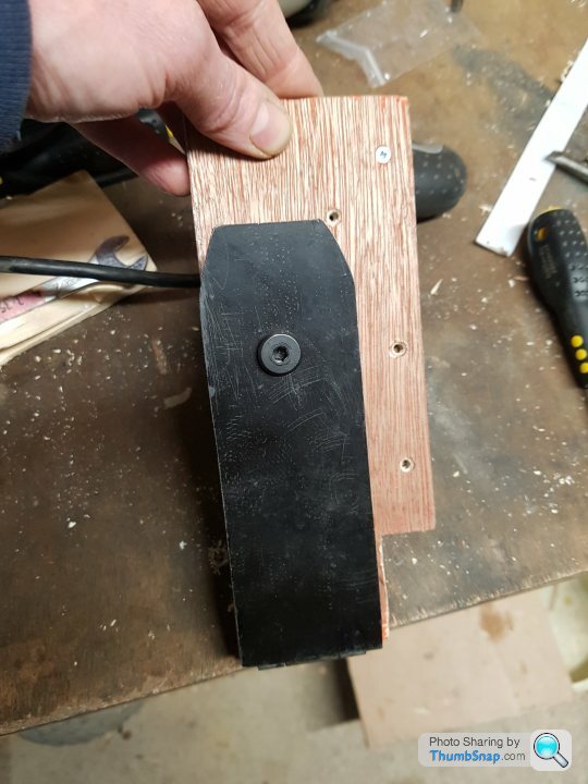
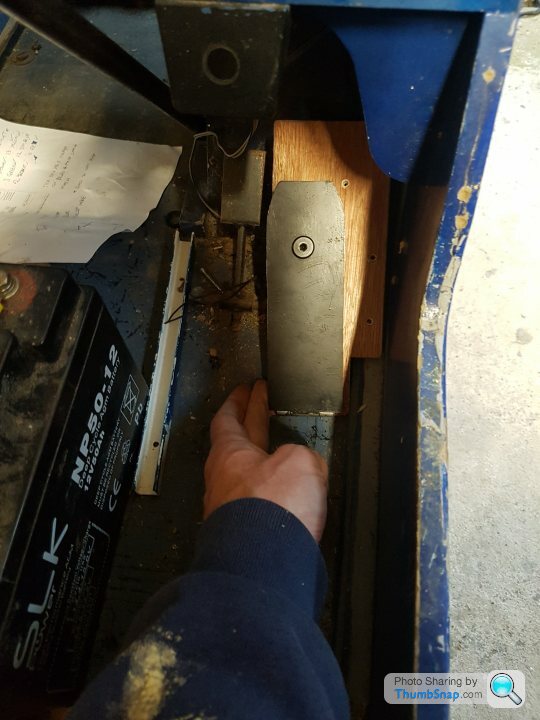
I've still been at this, in between the inevitable DIY jobs on the house. This the accelerator pedal that I built from the wig-wag pot on the mobility scooter. It is based on a design I came across on the Toylander forum, slightly adapted to suit my model of scooter. The M6 bolt acts as a plunger to push the wig-wag round.
It needs a little refinement; I will add a stop to prevent the driver trying to push the pedal beyond the wig-wag's stop. I'll probably add a compression spring below the pedal aswell together with another nut on the bolt so the pedal isn't just held up by the wig wag.
Pedal in the footwell
It needs a little refinement; I will add a stop to prevent the driver trying to push the pedal beyond the wig-wag's stop. I'll probably add a compression spring below the pedal aswell together with another nut on the bolt so the pedal isn't just held up by the wig wag.
Pedal in the footwell
I have to use Google to find this thread now 
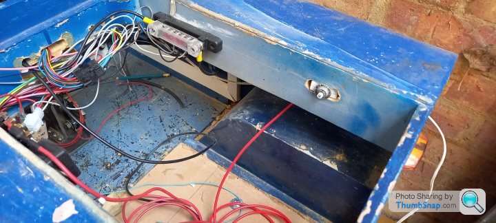
Picture of the "handbrake" below. Thus will enable the driver to select between being able to coast when lifting off the accelerator, or for the electric brakes to apply when lifting off. The latter is as per a standard mobility scooter.
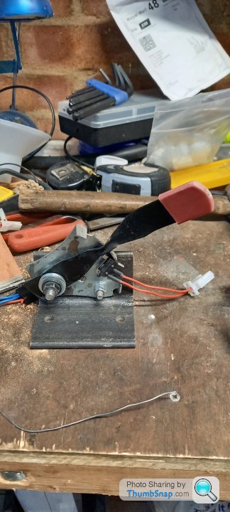
In a similar manner I have made a gear selector with reverse and 4mph/8mph microswitch. The large microswitch turns off the speed controller when moving into reverse so that tge driver can't throw it straight into reverse whilst still going forwards (I may have to bypass this when testing on muddy/snowy ground )
)
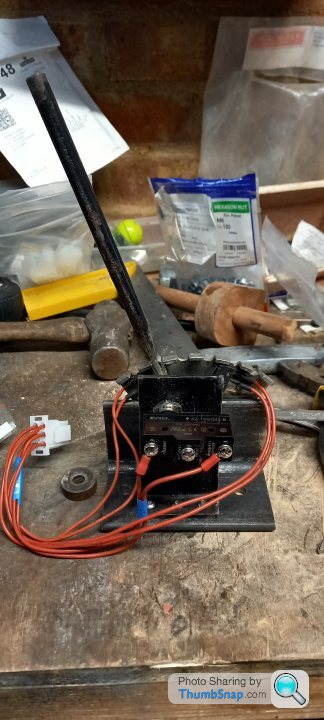
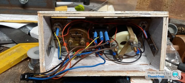
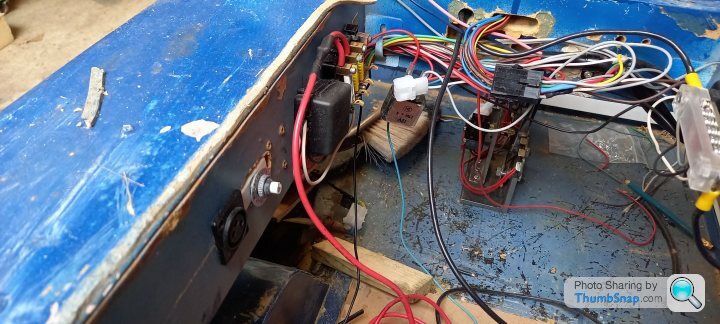
Relay boxes for handbrake, reverse and speed limiter.
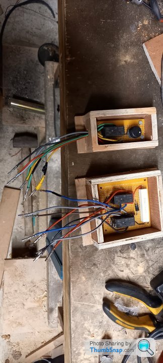
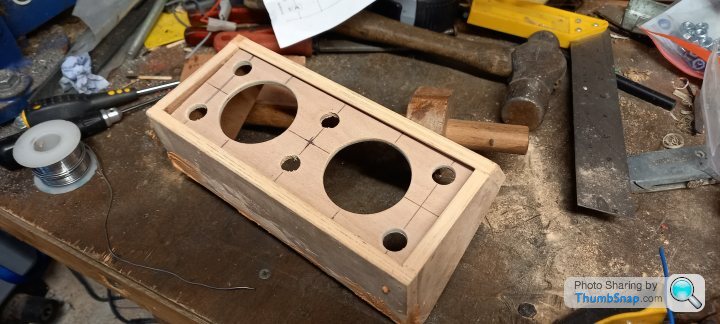
Instrument cluster casing.
Picture of the "handbrake" below. Thus will enable the driver to select between being able to coast when lifting off the accelerator, or for the electric brakes to apply when lifting off. The latter is as per a standard mobility scooter.
In a similar manner I have made a gear selector with reverse and 4mph/8mph microswitch. The large microswitch turns off the speed controller when moving into reverse so that tge driver can't throw it straight into reverse whilst still going forwards (I may have to bypass this when testing on muddy/snowy ground
)Relay boxes for handbrake, reverse and speed limiter.
Instrument cluster casing.
I'm slowly cracking on with this, the plan is to have it ready in April next year (between my two boys' birthdays).
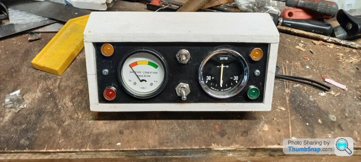
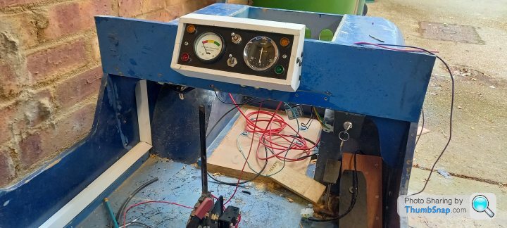
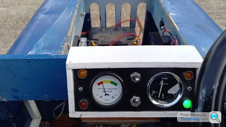
This is the complete instrument cluster, which is the last bespoke electrical component
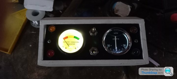
Lit up
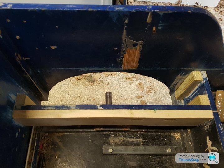
In a break from electrical work I removed the front axle from the car. Newer Toylanders have a tractor type swing axle on the front , however mine has the earlier rigidly mounted axle.
My local garage welded a piece of 16mm od, 12mm id steel tube into the axle.
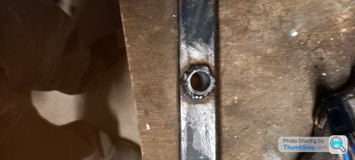
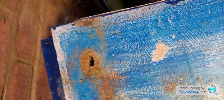
Old damage from the front bumper hitting a wall and the mounting hole becoming enlarged. Unfortunately there is a fair amount of water damage to the mdf. This will be reinforced with plywood glued to the inside.
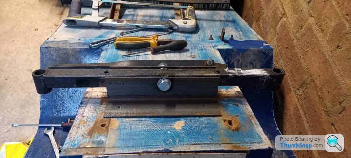
Front axle loosely positioned before marking the mounting holes.
Once the axle is mounted, I will be building and routing the wiring loom, ready to properly test the rolling shell. [
This is the complete instrument cluster, which is the last bespoke electrical component
Lit up
In a break from electrical work I removed the front axle from the car. Newer Toylanders have a tractor type swing axle on the front , however mine has the earlier rigidly mounted axle.
My local garage welded a piece of 16mm od, 12mm id steel tube into the axle.
Old damage from the front bumper hitting a wall and the mounting hole becoming enlarged. Unfortunately there is a fair amount of water damage to the mdf. This will be reinforced with plywood glued to the inside.
Front axle loosely positioned before marking the mounting holes.
Once the axle is mounted, I will be building and routing the wiring loom, ready to properly test the rolling shell. [
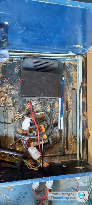
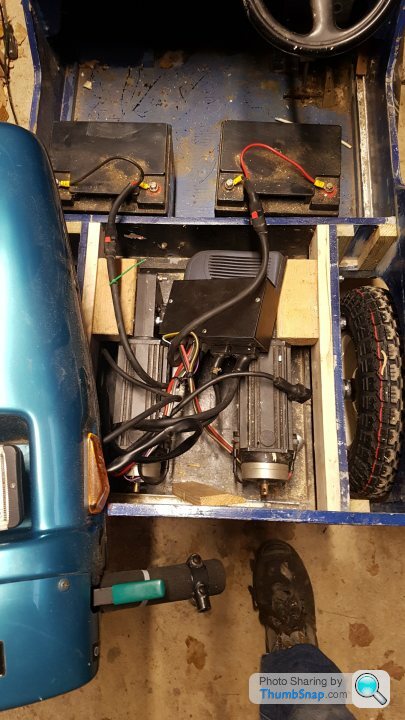
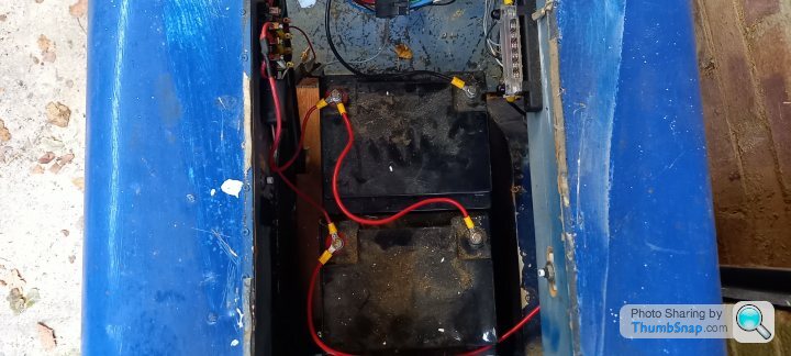
Motors now back in, and batteries fitted
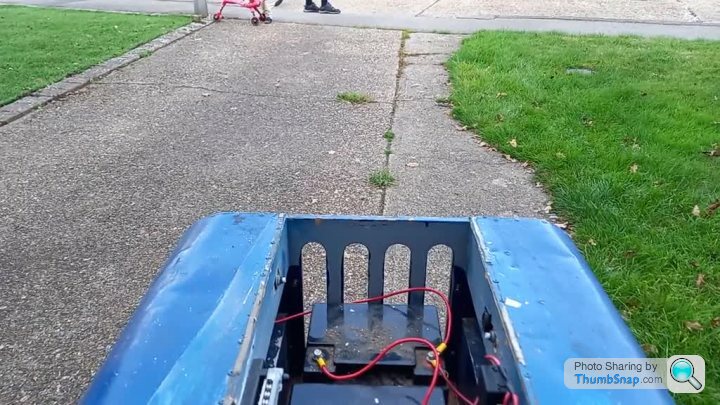
Creeping up the drive. Seems to track reasonably straight in spite of the front axle pivot being slightly skewed. I mounted the axle mounts slightly off the other way to compensate
Short test run. One battery is showing 11.9v fully charged hence the dash voltmeter being in the yellow/red
The chains click when it's reversing which may be an alignment issue. However they also have more slack on one side than the other, so they would probably benefit from some kind of guide on the slack side.
This winter's job is to strip it to a bare tub, do some body repairs and paint everything.
Love these Toylanders. I got the information pack sent to me years ago with the intention of making one for my sons. Unfortunately busy life meant I never got round to making it and my youngest at 16 and 6'2" is probably a wee bit too big now. Perhaps if grandchildren come along I'll build one for them in the future.
Bobupndown said:
Love these Toylanders. I got the information pack sent to me years ago with the intention of making one for my sons. Unfortunately busy life meant I never got round to making it and my youngest at 16 and 6'2" is probably a wee bit too big now. Perhaps if grandchildren come along I'll build one for them in the future.
I'm definitely lucky in that the body tub was built for me 30+ years ago! I think that back then Toylander supplied paper patterns to stick to the MDF for cutting the panels out.
Gassing Station | Readers' Cars | Top of Page | What's New | My Stuff