ECU Pins missing on schematics
Discussion


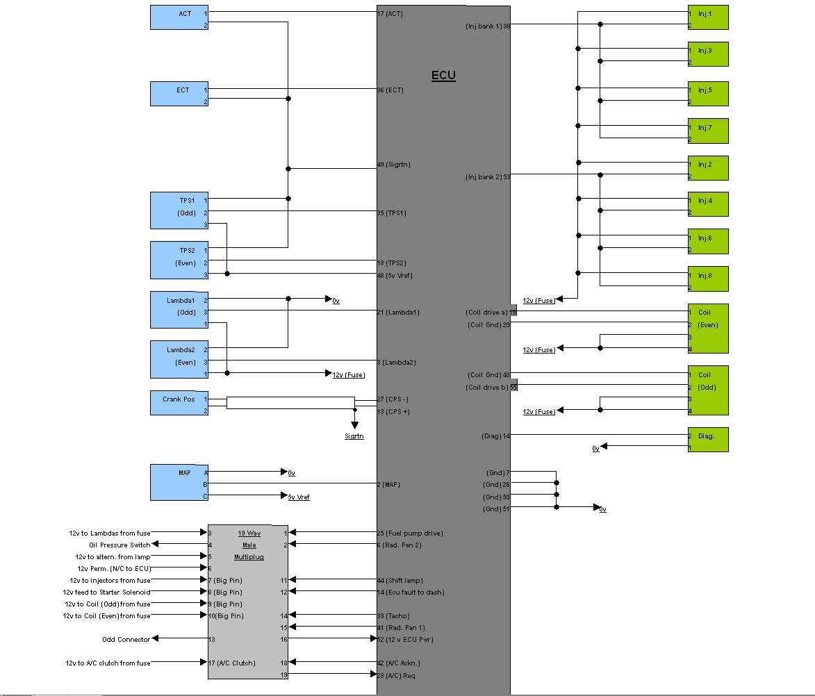
After rewwiring my ECU to go to something a bit more advanced I found 2 pins connected on the MBE but not shown on the TVR diagrams (any of them!).
Anyone know what pins 10 and 24 on the MBE 55 pin connector do. I think I have connected everything that is of any consequence. All my ECU sensor signals are there and coils/injectors connected including tacho, aircon and shift light etc. Still have two wores stuck out of the MBE connector and no idea what they might be for.
Anyone know what pins 10 and 24 on the MBE 55 pin connector do. I think I have connected everything that is of any consequence. All my ECU sensor signals are there and coils/injectors connected including tacho, aircon and shift light etc. Still have two wores stuck out of the MBE connector and no idea what they might be for.
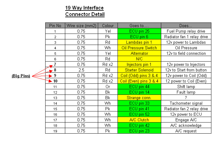
Hasn't got your pins on it though 
10 & 24 not shown wired on the wiring diagram
http://www.thetvrsite.com/files/wiring-diagrams/bo...
How about the stuff from SBD?
http://www.sbdev.co.uk/Engine_Management_Systems/E...
MBE SYSTEMS LTD
941-F WIRING HARNESS PIN OUT FOR V8 Engines
September 4, 1997 Issue 3
PIN NO. DESIGNATION NOTES
1 Stepper Motor ICV
2 Barometric Pressure Signal
3 Lambda 2 Signal
4 Fuel Pressure Signal
5 Afterburn Air bypass Valve
6 Gearshift Light
7 Power Ground
8 Not Used
9 Oil Temperature Signal
10 Ignition Trim
11 Not Used
12 Analog Ground
13 Crank Signal
14 Fault Lamp
15 Wastegate Valve Drive
16 Not Used
17 Air Temperature Signal
18 Boost Pressure Signal
19 Ignition Drive
20 Ignition Drive
21 Lambda 1 Signal
22 Gear Position Signal
23 Oil Pressure Signal
24 Engine Fault Lamp (Not Used)
25 Fuel Pump Relay
26 Power Ground
27 Crank Return
28 Boost Trim
29 Not Used
30 5V Analog
31 12V Sensor Supplies
32 Not Used
33 Tacho Signal
34 Not Used
35 Throttle Position Signal
36 Coolant Temperature Signal
37 Stepper Motor ICV
38 Ignition Drive
39 Stepper Motor ICV
40 Injector Drive Bank A
41 Radiator Fan Relay
42 Intercooler Spray Drive
43 Variable Intake Valve Drive
44 Variable Camshaft Timing
45 Serial Data Receive
46 Serial Data Transmit
47 Fuel Trim
48 5V Analog
49 0V Analog
50 Power Ground
51 Power Ground
52 ECU 12V Supply
53 Injector Drive Bank B
54 Stepper Motor ICV
55 Ignition Drive
Edited by Byker28i on Tuesday 30th May 13:01
fatjon said:
Anyone know what pins 10 and 24 on the MBE 55 pin connector do.
Any chance of a photo and/or the colour(s) of the two remaining wires?As mentioned above on the TVR wiring diagram they are shown as N/C, but I know from replacing the door wiring on my car that the early and later cars has wiring changes so we might be able to guess / work it out from that...
fatjon said:
That 941-f drawing is very different. I think the F is Ferrari and it was a unique one for them. I'll just see what doesn't work when my coil drivers arrive.
In fact the two are really very similar - here's a mapping of the 941-F drawing versus the TVR wiring diagramsThe main difference is that I'm guessing the Ferraris were turbo charged (?) as they have connections for "Boost Trim", "Wastegate Valve Drive" and "Afterburn Air bypass Value"
Were the MBE ECUs used in the Ferrari F40 by any chance as that's the only Ferrari from that era that I can seem to find that was turbo charged??
Anyway, in the table below the entries with the 2 spaces before are direct maps between the above table and the TVR Cerbera wiring diagram
The "y " indicates terminals that are meant to be not connected
The "x " indicates things that are different between the two
I do know that from the ECU software that the later versions had Oil Temperature so perhaps that is one of the inputs not mapped on the wiring diagram...
Also interestingly the Cerbera was separate wiring for 4 banks of 2 injectors in Connector 2, but pairs them together for Conector 3 when they reach the ECU as I'm guessing the MBE ECU can only cope with 2 inputs
In theory with an aftermarket or later ECU you could split these out and have:
INJ 1+7
INJ 3+5
INJ 4+6
INJ 2+8
1 Stepper Motor ICV [STEPPER 1 (CONN 2 = 23)(U)]
2 Barometric Pressure Signal (MAP) [PRESS SENSOR (CONN 4 = B)(U)]
3 Lambda 2 Signal (Lambda 2) [LAMBDA 2468 (CONN 2 = 14)(U)]
x 4 Fuel Pressure Signal [N/C]
x 5 Afterburn Air bypass Valve [N/C]
6 Gearshift Light (Rad. Fan 2) x [RADIATER FAN 2 (CONN 3 = 2)(K/G)]
7 Power Ground (GND) [EARTH TO BATTERY]
y 8 Not Used [N/C]
x 9 Oil Temperature Signal [N/C]
x 10 Ignition Trim ?? [N/C]
y 11 Not Used [N/C]
y 12 Analog Ground [N/C]
13 Crank Signal (CPS+) [CRANK SIGNAL (CONN 2 = 17)(WHITE CORE)]
14 Fault Lamp (Ecu fault to dash) (Diag) [FAULT LAMP (CONN 2 = 12)(BG)]
x 15 Wastegate Valve Drive [N/C]
y 16 Not Used [N/C]
17 Air Temperature Signal (ACT) [AIR TEMP. (CONN 2 = 22)(K)]
18 Boost Pressure Signal (TPS2) [T.POT EVEN (CONN 2 = 28)(O)]
19 Ignition Drive [IGN 4+6 SIG (CONN 2 = 34)(K)]
20 Ignition Drive [IGN 2+8 SIG (CONN 2 = 35)(W)]
21 Lambda 1 Signal (Lambda 1) [LAMBDA 1357 (CONN 2 = 27)(Y)]
x 22 Gear Position Signal [N/C]
23 Oil Pressure Signal (A/C Req) x [A/C REQUEST (CONN 3 = 19)(W/K)]
x 24 Engine Fault Lamp (Not Used) ?? [N/C]
25 Fuel Pump Relay (Fule pump drive) [FUEL PUMP (CONN 3 = 1)(Y)]
26 Power Ground (GND) [EARTH TO BATTERY]
27 Crank Return (CPS-) [CRANK RETURN (CONN 2 = 16)(BLACK CORE)]
x 28 Boost Trim [N/C]
y 29 Not Used [N/C]
y 30 5V Analog [N/C]
y 31 12V Sensor Supplies [N/C]
y 32 Not Used [N/C]
33 Tacho Signal (Tacho) [TACHO SIGNAL (CONN 3 = 14)(W/B)]
y 34 Not Used [N/C]
35 Throttle Position Signal (TPS1) [T.POT ODD (CONN 2 = 15)(O)]
36 Coolant Temperature Signal (ECT) [WATER TEMP (CONN 2 = 21)(U)]
37 Stepper Motor ICV [STEPPER 2 (CONN2 = 24(O))]
38 Ignition Drive (Inj bank 1) [INJ 1+7 SIG (CONN 2 = 6), INJ 3+5 SIG (CONN 2 = 9) (O)]
39 Stepper Motor ICV [STEPPER 3 (CONN 2 = 25 (Y))]
40 Injector Drive Bank A (Coil Gnd) [IGN 1+7 SIG (CONN 2 = 1)(Y)]
41 Radiator Fan Relay (Rad. Fan 1) [RADIATER FAN(CONN 3 = 15 (K/G))]
42 Intercooler Spray Drive (A/C Ackn.) x [A/C ACKNOWLEDGE (CONN 3 = 18 (W/B))]
x 43 Variable Intake Valve Drive [N/C]
44 Variable Camshaft Timing (Shift lamp) x [SHIFT LAMP (CONN 3 = 11 (O))]
y 45 Serial Data Receive [N/C]
y 46 Serial Data Transmit [N/C]
x 47 Fuel Trim [N/C]
48 5V Analog (V5 Vref) [+5V (CONN2 = 20)]
49 0V Analog (Sigrtn) [0V (CONN 2 = 19)]
50 Power Ground (GND) [EARTH TO BATTERY]
51 Power Ground (GND) [EARTH TO BATTERY]
52 ECU 12V Supply (12 v ECU Pwr) [ECU +12V (CONN 3 = 16 (W))]
53 Injector Drive Bank B (Inj bank 2) [INJ 4+6 SIG (CONN 2 = 33), INJ 2+8 SIG (CONN 2 = 30)]
54 Stepper Motor ICV [STEPPER 4 (CONN 2 = 25)]
55 Ignition Drive (Coil drive b) [IGN 3+5 SIG (CONN 2 = 2)]
fatjon said:
After rewwiring my ECU to go to something a bit more advanced I found 2 pins connected on the MBE but not shown on the TVR diagrams (any of them!).
Anyone know what pins 10 and 24 on the MBE 55 pin connector do. I think I have connected everything that is of any consequence. All my ECU sensor signals are there and coils/injectors connected including tacho, aircon and shift light etc. Still have two wores stuck out of the MBE connector and no idea what they might be for.
@fatjon Any update on what these two pins were connected to?Anyone know what pins 10 and 24 on the MBE 55 pin connector do. I think I have connected everything that is of any consequence. All my ECU sensor signals are there and coils/injectors connected including tacho, aircon and shift light etc. Still have two wores stuck out of the MBE connector and no idea what they might be for.
Largely out of curiosity but as a group of us are working on some ECU software it would be good to know to incorporate - I was wondering one was for Oil Pressure which I think is supported in the last of V8 ECU versions and the S6 ones?
Update:
not a clue where they go and everything works just fine without them! All the sensors, injectors, aircon, barometric sensor, tacho, fans, MIL light, shift light all work just fine.
My next step is to meter them and see what I find in terms of voltages or signals and see if they offer any clues. I am intending to change the oil sensor for a 0-5v unit so I can log oil pressure but that's coming later. My immediate task is adding stepper motor based idle speed control which is on the TVR schematics but never made it onto the car.

The luxury of having car with performance and manners is just so appealing. Might even have a play with traction control later or maybe that's a step too civilised?
not a clue where they go and everything works just fine without them! All the sensors, injectors, aircon, barometric sensor, tacho, fans, MIL light, shift light all work just fine.
My next step is to meter them and see what I find in terms of voltages or signals and see if they offer any clues. I am intending to change the oil sensor for a 0-5v unit so I can log oil pressure but that's coming later. My immediate task is adding stepper motor based idle speed control which is on the TVR schematics but never made it onto the car.
The luxury of having car with performance and manners is just so appealing. Might even have a play with traction control later or maybe that's a step too civilised?
I have just noticed a wire called "Alternator" on the TVR schematics too (see above picture). That does not exist on my car, no wire on that pin. I wonder if there was also a plan to use an ECU controlled alternator too at some point? I won't be doing that though, if it works leave it alone.
Edit, talking rubbish, that's not the ECU connector! Must drink coffee before trying to think.
Edit, talking rubbish, that's not the ECU connector! Must drink coffee before trying to think.
fatjon said:
My immediate task is adding stepper motor based idle speed control which is on the TVR schematics but never made it onto the car.
The luxury of having car with performance and manners is just so appealing. Might even have a play with traction control later or maybe that's a step too civilised?
Interesting - just had a read around this and it looks like the Chimera had a stepper motor installed to control the idle but as you say that was never connected or installed on the CerberaThe luxury of having car with performance and manners is just so appealing. Might even have a play with traction control later or maybe that's a step too civilised?
I'm not actually sure therefore whether the software even sends any outputs to those pins?
Might be worth metering them while you are testing the other undocumented pins to see if they increase voltage over time / turn +5V/+12V so that they would actually increase the turn on the stepper motor or not?
The MBE ECU doesn't have anything connected to those pins so I doubt the code to run them exists in it. My new ECU does support stepper idle control but there are some difficulties applying it on the 4.5 engine as the injectors are above the throttle plates and there's no measurement of manifold vacuum and therefore nothing to use a reference for idle fueling. This semi precludes using an air bypass valve for idle control.
If I fully close the throttles and use only an air bypass valve their will be no fuel, just a puddle on top of the plates and as I open and close an air bypass valve there is no signal to add or remove fuel as the TPS will not move. This probably means that the only way to regulate idle speed is by directly controlling the throttle plates. Maybe I can use the lambda sensors to compensate but that's a bit hit and miss. At the moment I'm thinking about how to use a geared stepper to get the super fine resolution needed to control idle using the throttle plates. Pretty sure it will need to be geared as a standard 1.8 degree stepper is way too coarse for the job.
Car is running better than it ever has and was holding an even 88- 92 degrees over the weekend, even when stuck in traffic. I have had it bump up the idle advance when it's hot to reduce the heat output (standard timing is very retarded at idle) and that ups the idle speed by 200 RPM which seems to have a big effect on the efficiency of the water pump. I noticed before on the Emerald that the counter-intuitive method of applying a little bit of throttle when it's getting hot in traffic helped so I have just automated that process.
Still need to spend some time putting timing marks on front of the engine so I can have more confidence in the timing before I take it over to Joolz for a dyno session but it was just too bloody hot this weekend for any king of manual labour around a hot engine so that will have to wait until next weekend.
Gassing Station | Cerbera | Top of Page | What's New | My Stuff