
Advice for first attempt at improving cylinder head flow
Discussion


Dear all,
Having followed the recent threads about porting heads and having just signed myself up for a local race series I was after some advice. The series is held on an old military airfield and is locally organised, run and controlled. I already have a trackday Golf Mk2 and am planning to incorporate the changes required by the rules but was thinking about trying to maximise the engine. The rules prohibit changes to the cam, inlet or exhaust manifolds and the ecu must remain standard. This is deliberate to e sure affordable racing and to try to minimise any advantages that can be gained simply by spending vast amounts of cash.
The engine in my car is a standard 1.8 8v and should have made about 110 hp when new, or so VW claimed at the time. This would place me in the 91 - 120 hp class and I am happy to stay here, at least for my first season. The engine has covered about 175k miles and I do not want to change too much. I have bought a spare head to play with and was wondering if there are any tips about how to ensure that I have all the horses originally specified and possibly 1 or 2 extra, as long as I don't break that 120 hp barrier. The next class is unlimited so I don't want to stray in there just yet.
I was thinking that port matching the manifolds and smoothing out any casting or manufacturing marks would be a start but would welcome any advice, both on tool choices and the practical aspects of doing this. As you can tell I am very new to this sort of modification, but want to try to learn as I go.
Many thanks in advance,
Jon
Having followed the recent threads about porting heads and having just signed myself up for a local race series I was after some advice. The series is held on an old military airfield and is locally organised, run and controlled. I already have a trackday Golf Mk2 and am planning to incorporate the changes required by the rules but was thinking about trying to maximise the engine. The rules prohibit changes to the cam, inlet or exhaust manifolds and the ecu must remain standard. This is deliberate to e sure affordable racing and to try to minimise any advantages that can be gained simply by spending vast amounts of cash.
The engine in my car is a standard 1.8 8v and should have made about 110 hp when new, or so VW claimed at the time. This would place me in the 91 - 120 hp class and I am happy to stay here, at least for my first season. The engine has covered about 175k miles and I do not want to change too much. I have bought a spare head to play with and was wondering if there are any tips about how to ensure that I have all the horses originally specified and possibly 1 or 2 extra, as long as I don't break that 120 hp barrier. The next class is unlimited so I don't want to stray in there just yet.
I was thinking that port matching the manifolds and smoothing out any casting or manufacturing marks would be a start but would welcome any advice, both on tool choices and the practical aspects of doing this. As you can tell I am very new to this sort of modification, but want to try to learn as I go.
Many thanks in advance,
Jon
You wont get the info you need here. You'll have better chance finding it in books. They'll have more detail, images etc of what needs done.
In the case of headwork, less is more. The less you do, you have lesser chance of making a mess, and more chance of improving things.
But who's to say the work you do wont see the engine make more than 120hp ? How exactly is that rule being enforced ?
Not sure if any books specific to your Golf exist. But something like this generic book might help
http://www.amazon.co.uk/How-Build-Horsepower-Metho...
Or if either of the two Dave's come along, they could maybe advise better.
Or perhaps this one.
http://www.amazon.co.uk/Build-Modify-Power-Cylinde...
In the world of the internet, it's very easy to overlook the value of written texts.
In the case of headwork, less is more. The less you do, you have lesser chance of making a mess, and more chance of improving things.
But who's to say the work you do wont see the engine make more than 120hp ? How exactly is that rule being enforced ?
Not sure if any books specific to your Golf exist. But something like this generic book might help
http://www.amazon.co.uk/How-Build-Horsepower-Metho...
Or if either of the two Dave's come along, they could maybe advise better.
Or perhaps this one.
http://www.amazon.co.uk/Build-Modify-Power-Cylinde...
In the world of the internet, it's very easy to overlook the value of written texts.

The most important question:
Do the series regulation allow "removal or addition of material" to the std cylinder head, intake, and exhaust components ??
Most "limited" series expressely forbid removal of material, meaning if you want to match intake manifold to ports you have to buy say 10 sets of everything and find the 2 parts with the best fit etc.........
Do the series regulation allow "removal or addition of material" to the std cylinder head, intake, and exhaust components ??
Most "limited" series expressely forbid removal of material, meaning if you want to match intake manifold to ports you have to buy say 10 sets of everything and find the 2 parts with the best fit etc.........
Before you go optimising head flow, I think with an engine that has covered 175K that you might want to ask if the engine needs a rebuild or not. I would think it probably does.
If the regs don't permit port material....
If it does I would think that they would at least allow you to 'fix' your engine, in which case some decent valves and cleverly cut seats would help. Select the machine shop by ability and not price if you want to win.
You could also skim the head - a lot.
The best investment would be to set the cam timing and optimise ignition and fuelling on a rolling road. When I say optimise cam timing, I don't mean set it to what the factory said it should be, but rather to get it to where the top end power is the most.
This is one of those occasions where the best advice might be to hand the project over to a Pumaracing type guy and let him do the work - freeing you up to prep the car and do all the other work.
If the regs don't permit port material....
If it does I would think that they would at least allow you to 'fix' your engine, in which case some decent valves and cleverly cut seats would help. Select the machine shop by ability and not price if you want to win.
You could also skim the head - a lot.
The best investment would be to set the cam timing and optimise ignition and fuelling on a rolling road. When I say optimise cam timing, I don't mean set it to what the factory said it should be, but rather to get it to where the top end power is the most.
This is one of those occasions where the best advice might be to hand the project over to a Pumaracing type guy and let him do the work - freeing you up to prep the car and do all the other work.
GavinPearson said:
Before you go optimising head flow, I think with an engine that has covered 175K that you might want to ask if the engine needs a rebuild or not. I would think it probably does.
If the regs don't permit port material....
If it does I would think that they would at least allow you to 'fix' your engine, in which case some decent valves and cleverly cut seats would help. Select the machine shop by ability and not price if you want to win.
You could also skim the head - a lot.
The best investment would be to set the cam timing and optimise ignition and fuelling on a rolling road. When I say optimise cam timing, I don't mean set it to what the factory said it should be, but rather to get it to where the top end power is the most.
This is one of those occasions where the best advice might be to hand the project over to a Pumaracing type guy and let him do the work - freeing you up to prep the car and do all the other work.
The Regs simply state that the original cams, manifolds and ecu must be retained. They also state that a car can be required to attend a RR to verify power outputs and thus competition Class. I am not looking to create a large power gain, just try to ensure that I have the original 110 (or so) hp reliably. I was thinking that I would also purchase a spare short engine and get the internals balanced, as long as that does not turn out to be too expensive. I would love to hand over a head to PumaRacing but do not have the budget, the ambition of sufficient additional power or the driving talent to make it worth his while. If I needed a lot more power then I would transplant an ABF engine in and run in the Unlimited Class. I am merely looking to see if I, an aging enthusiast with no previous skill or experience, can get the best out of a cylinder-head with a little fettling around the edges.If the regs don't permit port material....
If it does I would think that they would at least allow you to 'fix' your engine, in which case some decent valves and cleverly cut seats would help. Select the machine shop by ability and not price if you want to win.
You could also skim the head - a lot.
The best investment would be to set the cam timing and optimise ignition and fuelling on a rolling road. When I say optimise cam timing, I don't mean set it to what the factory said it should be, but rather to get it to where the top end power is the most.
This is one of those occasions where the best advice might be to hand the project over to a Pumaracing type guy and let him do the work - freeing you up to prep the car and do all the other work.
Many thanks for the responses so far,
Jon
Jonleeper said:
They also state that a car can be required to attend a RR to verify power outputs and thus competition Class.
Jon
That could be a huge can of worms. Dynos can be manipulated to read whatever people want them to read, so are not a reliable method.Jon
They would need to test every single car in the race series on the same day, same weather conditions and ensure the dyno operator isnt messing with things to fudge any readings.
In short, it would be impossible to regulate a race series by that method. And which dyno are they using as the benchmark for any numbers ? Every dyno will be different, and some read much higher or lower than others.
I would follow the advice given.
Cylinder head porting is not simple and is not all about absolute flow. It is a very complex procedure and one that is usually best practiced via trial and error.
If i wanted the best from an engine a full rebuild and clean out would be beneifical as well as a decent airfilter.
Chris
Cylinder head porting is not simple and is not all about absolute flow. It is a very complex procedure and one that is usually best practiced via trial and error.
If i wanted the best from an engine a full rebuild and clean out would be beneifical as well as a decent airfilter.
Chris
varnish5000 said:
might be helpful:
http://www.clubgti.com/forum/showthread.php?t=2027...
At work at the moment, but that looks great.http://www.clubgti.com/forum/showthread.php?t=2027...
Many thanks,
Jon
stevieturbo said:
Jonleeper said:
They also state that a car can be required to attend a RR to verify power outputs and thus competition Class.
Jon
That could be a huge can of worms. Dynos can be manipulated to read whatever people want them to read, so are not a reliable method.Jon
They would need to test every single car in the race series on the same day, same weather conditions and ensure the dyno operator isnt messing with things to fudge any readings.
In short, it would be impossible to regulate a race series by that method. And which dyno are they using as the benchmark for any numbers ? Every dyno will be different, and some read much higher or lower than others.
Jonleeper said:
The series is, in reality, little more than a group of "friends" who use an airfield to engage in some controlled competitive driving. Regulation is more of a don't do anything that we can either see or is obvious otherwise we will take you to a rolling road and see what's what. I do not want to cheat at all I am just looking to get the best I can from my engine within the 90-120hp bracket. I am not a racing driver and am unlikely to challenge the established order too much, well I hope too but think that might just be a forlorn hope. ;-) I think that I will just clean up the head and see where we go from there.
Spend the money on getting a bottom end rebuild.Right I have read this thread, got that suggested reading and started that and looked through the linked Golf thread as well. The engine is a VW PB code 1.8l with an 8 valve head. It has a bore of 81mm and a stroke of 86.4mm.
As a start I have done the calculations, based on Pumaracing’s knowledge, and got the following.
Inlets valve size = 40mm
Exhaust valve size = 33mm
Thus I need to cut the inlet seat as follows:
22.5 deg top cut
45 deg seat = 1.8mm (4.5% of valve OD)
70 deg bottom cut
This should give a throat of 34.4mm (86% of valve OD)
The exhaust seat should be:
20-30 deg top cut
45 deg seat = 1.8mm (same as inlet but now 5.45% of valve OD)
70 deg bottom cut
This should give a throat size of 29.04mm (88% of valve OD)
I also need to get a 30 deg backcut an all valves before I reassemble the engine. There is, apparently, a good engine builders in Gutersloh who can carry out all this work so I’ll be investigating this option a bit further in due course.
I have also unwrapped my spare head and removed the cam, valves, etc and so have had my first look at a “bare” cylinder head. I did not take my camera down to the garage last night but will do today and should be able to post up some photos later. On first sight the looks to be a small lip between the bottom of the valve seat and the actual head but I could not feel any ridge with a fingertip. There is also a prominent ridge under the seat but before the valve guide boss that would appear to be adding nothing except an intrusion onto the smooth flow. There is also clear evidence on the side of the head of the difference between the gaskets and head port size. I am thinking that this sudden change in size/shape can only be detracting from smooth flow and should be smoothed. It if wasn’t then there would not be a build up of deposit at this point as the air slows.
I am a complete novice at this, if that is not obvious by now, and so am only going to go very slowly. My first thoughts, based on what I have read, is to smooth the join between the valve seat and the head and then look again to see what else can be done without destroying too much of the work VW put into designing the head in the first place.
I will try to post pictures later for additional comment,
Jon
As a start I have done the calculations, based on Pumaracing’s knowledge, and got the following.
Inlets valve size = 40mm
Exhaust valve size = 33mm
Thus I need to cut the inlet seat as follows:
22.5 deg top cut
45 deg seat = 1.8mm (4.5% of valve OD)
70 deg bottom cut
This should give a throat of 34.4mm (86% of valve OD)
The exhaust seat should be:
20-30 deg top cut
45 deg seat = 1.8mm (same as inlet but now 5.45% of valve OD)
70 deg bottom cut
This should give a throat size of 29.04mm (88% of valve OD)
I also need to get a 30 deg backcut an all valves before I reassemble the engine. There is, apparently, a good engine builders in Gutersloh who can carry out all this work so I’ll be investigating this option a bit further in due course.
I have also unwrapped my spare head and removed the cam, valves, etc and so have had my first look at a “bare” cylinder head. I did not take my camera down to the garage last night but will do today and should be able to post up some photos later. On first sight the looks to be a small lip between the bottom of the valve seat and the actual head but I could not feel any ridge with a fingertip. There is also a prominent ridge under the seat but before the valve guide boss that would appear to be adding nothing except an intrusion onto the smooth flow. There is also clear evidence on the side of the head of the difference between the gaskets and head port size. I am thinking that this sudden change in size/shape can only be detracting from smooth flow and should be smoothed. It if wasn’t then there would not be a build up of deposit at this point as the air slows.
I am a complete novice at this, if that is not obvious by now, and so am only going to go very slowly. My first thoughts, based on what I have read, is to smooth the join between the valve seat and the head and then look again to see what else can be done without destroying too much of the work VW put into designing the head in the first place.
I will try to post pictures later for additional comment,
Jon
The valve seats as I suggest will give you a starting point but the critical part of this head is the short side bend on the inlet port. This needs cutting back as far as posible to increase the radius but there's a waterway just behind it and if you go too far you'll break through into this. It's a very difficult head to get just right.
You can forget matching manifolds to ports. That'll make no difference whatsoever.
As stock the head only flows 123 cfm which is pitiful for the valve size. It's about the worst flowing 2v head I've ever come across with a discharge coefficient of only 0.43. I can get this up to over 160 cfm but that's still crap. The waterways stop you dead in what you'd really like to achieve.
You can forget matching manifolds to ports. That'll make no difference whatsoever.
As stock the head only flows 123 cfm which is pitiful for the valve size. It's about the worst flowing 2v head I've ever come across with a discharge coefficient of only 0.43. I can get this up to over 160 cfm but that's still crap. The waterways stop you dead in what you'd really like to achieve.
So as promised I took some photos to show what I have done / am attempting to do. All work was done with a Dremel Pro and a variety of bits I already had.
First a look at the head before work commenced:
In this first shot you can see the overall condition of the head. I have specifically checked, visually, for any cracks between the valve seats and generally for any evidence of cracking elsewhere.
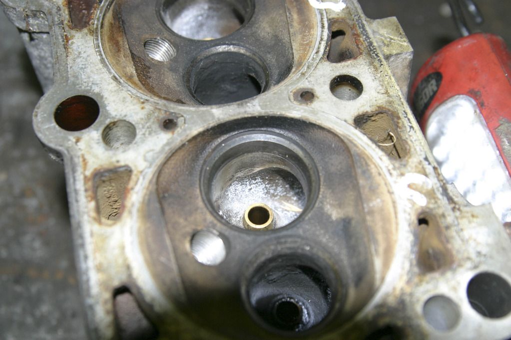
This is a closer look at the valve seat and you can see that there is a ridge between the base of the seat and the throat.
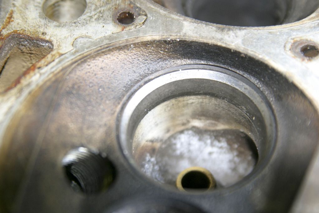
Here I have tried to show that there is a prominent ridge on the wall of the bowl behind the valve guide boss. There are also casting marks / burrs across the port that can be felt with my finger.
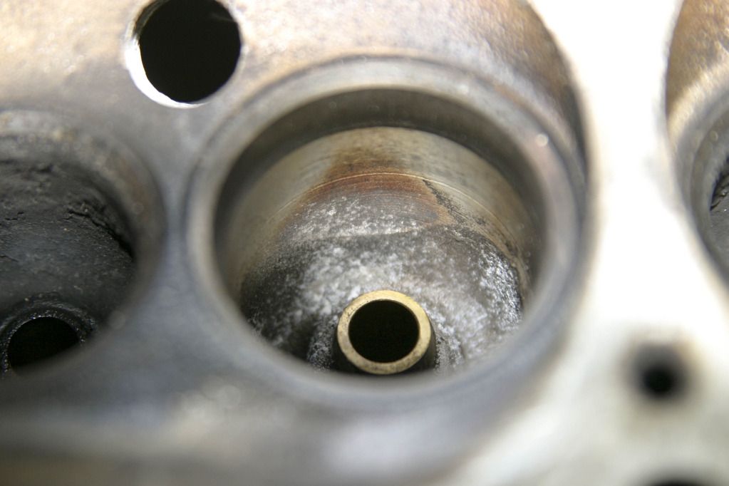
For my first attempt all I have tried to do is smooth out the obvious casting marks and blend the ridge into the wall of the port. I used some small carbide tips i had and a speed of 22000 rpm. This seemed fine with gentle pressure and a bit of patience.
The initial results are as follows:
I first tried to blend the valve seat into the throat to get a continuous surface. This was achieved by gently grinding the join until there was a continuous colour change across the whole of the area. When I started there was an obvious line where the two surfaces did not match and I slowly worked until it felt smooth and looked continuous.
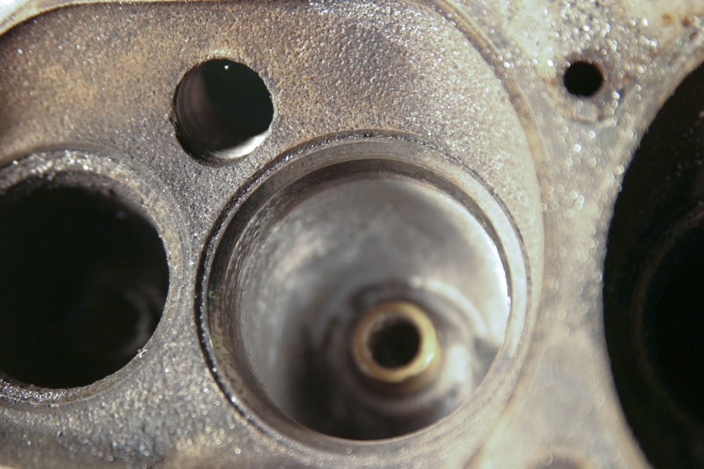
Next I delved deeper into the bowl and smoothed out the prominent ridge at the back of the valve guide boss. This took a bit of time, cutting then feeling then cutting then feeling etc, but eventually i got a result that i am happy with. It is not perfectly smooth and the ridge can still, just, be felt but it is much smoother than it was.
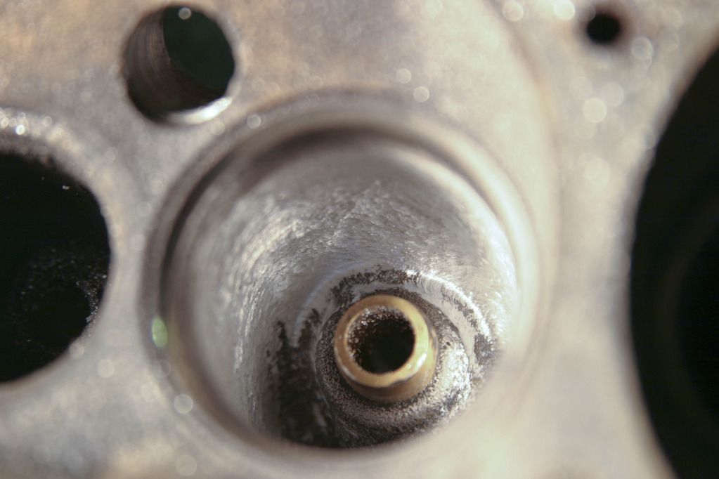
I then turned my attention to the inlet. Here there was a very prominent casting burr running down each side into the port. I smoothed these out on both sides.
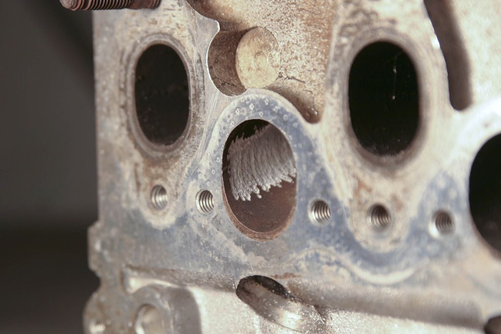
I then slowed down the speed and fitted a stone to try and further smooth out the walls of the port. The results are as follows:
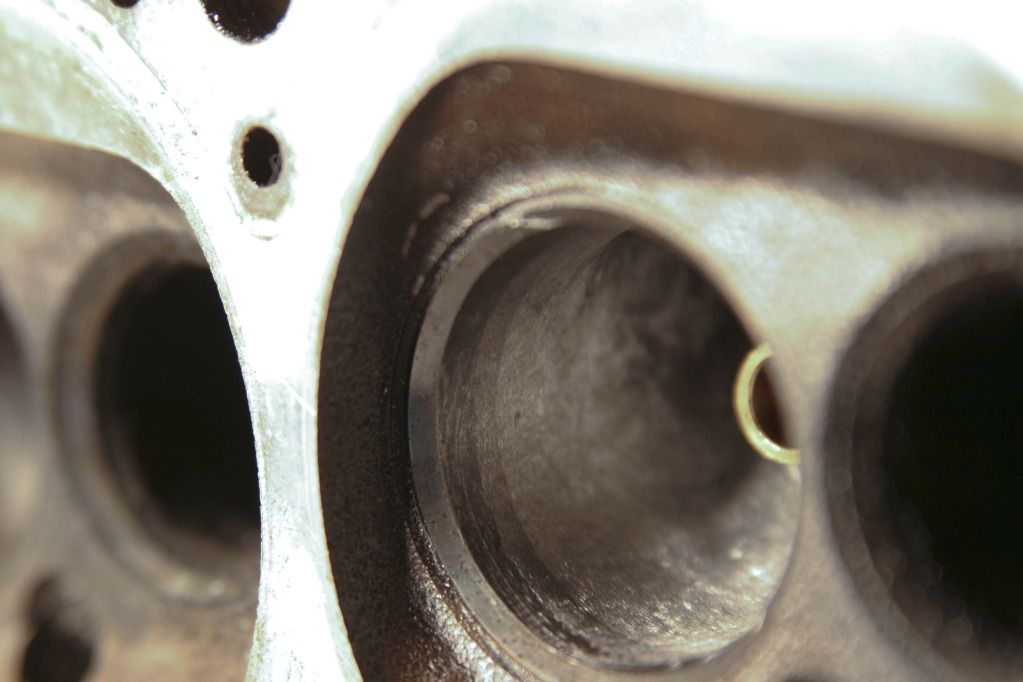
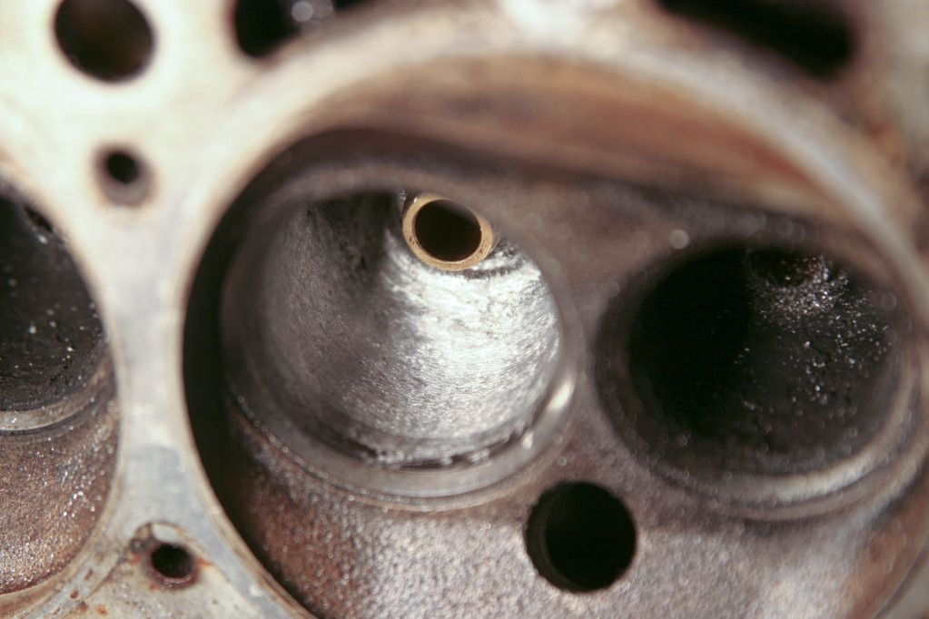
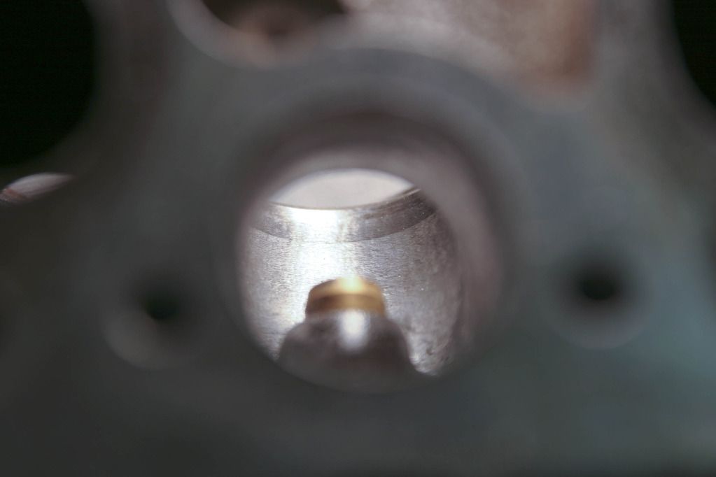
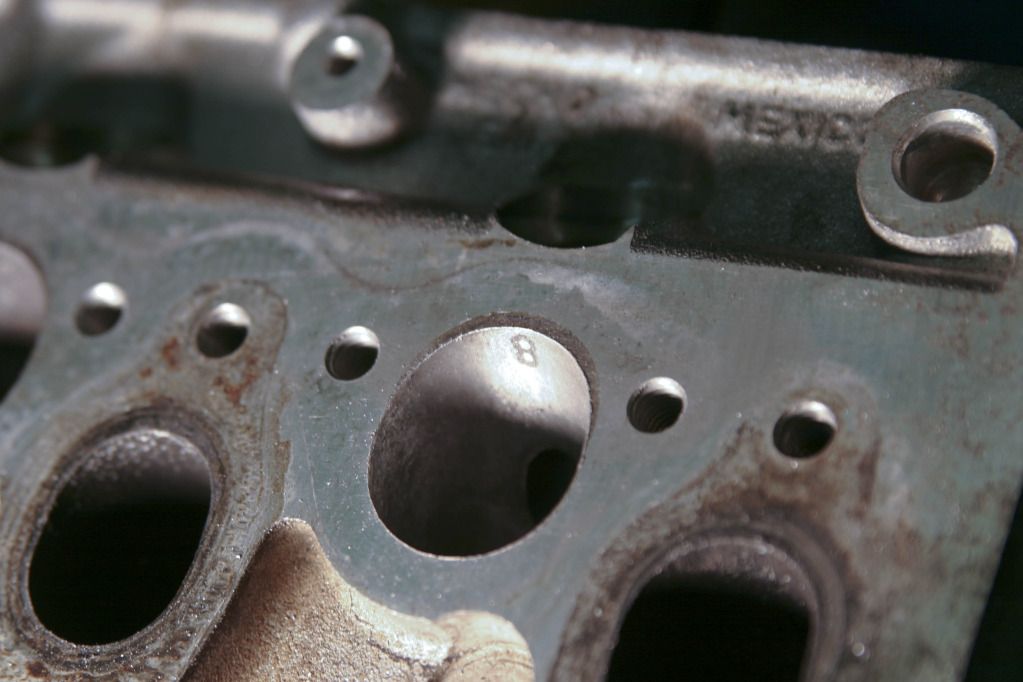
I am sure that there is much more that could be achieved, i am just trying to go slowly and learn as I go.
Over to you all for comment / critique!
Jon
First a look at the head before work commenced:
In this first shot you can see the overall condition of the head. I have specifically checked, visually, for any cracks between the valve seats and generally for any evidence of cracking elsewhere.
This is a closer look at the valve seat and you can see that there is a ridge between the base of the seat and the throat.
Here I have tried to show that there is a prominent ridge on the wall of the bowl behind the valve guide boss. There are also casting marks / burrs across the port that can be felt with my finger.
For my first attempt all I have tried to do is smooth out the obvious casting marks and blend the ridge into the wall of the port. I used some small carbide tips i had and a speed of 22000 rpm. This seemed fine with gentle pressure and a bit of patience.
The initial results are as follows:
I first tried to blend the valve seat into the throat to get a continuous surface. This was achieved by gently grinding the join until there was a continuous colour change across the whole of the area. When I started there was an obvious line where the two surfaces did not match and I slowly worked until it felt smooth and looked continuous.
Next I delved deeper into the bowl and smoothed out the prominent ridge at the back of the valve guide boss. This took a bit of time, cutting then feeling then cutting then feeling etc, but eventually i got a result that i am happy with. It is not perfectly smooth and the ridge can still, just, be felt but it is much smoother than it was.
I then turned my attention to the inlet. Here there was a very prominent casting burr running down each side into the port. I smoothed these out on both sides.
I then slowed down the speed and fitted a stone to try and further smooth out the walls of the port. The results are as follows:
I am sure that there is much more that could be achieved, i am just trying to go slowly and learn as I go.
Over to you all for comment / critique!
Jon
I'm afraid that what you think is impeding flow is really making very little difference to it. Perhaps the blending of the step under the valve seat insert is worth a cfm or so but the rest is achieving nothing. The air doesn't care about casting marks in the port or lines in the valve throat.
The critical area is clear to see from one of your pics. As I've already said the short side bend in the inlet port is where all the flow is gained or lost in that head. That sharp edge that VW created when they bored down the throat is killing flow bigtime. You need to round that off to the largest radius possible starting from just under the seat insert and blending it back into the straight part of the port. It needs a lot of metal removal and if you go too far you'll find a waterway. However even a cursory smooth off will add plenty of cfm. It's almost impossible to make it worse even if you have no clue what you're doing.
Here's the flow figures from the Slick 50 heads I used to work on. The first column is stock. The 2nd is what most people were using done by a fairly decent well known head specialist to get 160 bhp or so. The 3rd column is mine with which we hit 180 bhp. You won't get anywhere near even the second column I'm afraid with a Dremel, no flowbench and no experience but you might get into the 130s cfm and add 10 or so bhp to the engine which is all you are after.
LIFT
THOU---STOCK--PACK D--PUMA
100----43.5---46.0----49.5
200----81.6---86.9----94.7
300---112.1--118.0---125.3
400---123.1--141.1---144.2
500---123.5--148.0---162.4
The critical area is clear to see from one of your pics. As I've already said the short side bend in the inlet port is where all the flow is gained or lost in that head. That sharp edge that VW created when they bored down the throat is killing flow bigtime. You need to round that off to the largest radius possible starting from just under the seat insert and blending it back into the straight part of the port. It needs a lot of metal removal and if you go too far you'll find a waterway. However even a cursory smooth off will add plenty of cfm. It's almost impossible to make it worse even if you have no clue what you're doing.
Here's the flow figures from the Slick 50 heads I used to work on. The first column is stock. The 2nd is what most people were using done by a fairly decent well known head specialist to get 160 bhp or so. The 3rd column is mine with which we hit 180 bhp. You won't get anywhere near even the second column I'm afraid with a Dremel, no flowbench and no experience but you might get into the 130s cfm and add 10 or so bhp to the engine which is all you are after.
LIFT
THOU---STOCK--PACK D--PUMA
100----43.5---46.0----49.5
200----81.6---86.9----94.7
300---112.1--118.0---125.3
400---123.1--141.1---144.2
500---123.5--148.0---162.4
Pumaracing said:
I'm afraid that what you think is impeding flow is really making very little difference to it. Perhaps the blending of the step under the valve seat insert is worth a cfm or so but the rest is achieving nothing. The air doesn't care about casting marks in the port or lines in the valve throat.
The critical area is clear to see from one of your pics. As I've already said the short side bend in the inlet port is where all the flow is gained or lost in that head. That sharp edge that VW created when they bored down the throat is killing flow bigtime. You need to round that off to the largest radius possible starting from just under the seat insert and blending it back into the straight part of the port. It needs a lot of metal removal and if you go too far you'll find a waterway. However even a cursory smooth off will add plenty of cfm. It's almost impossible to make it worse even if you have no clue what you're doing.
Here's the flow figures from the Slick 50 heads I used to work on. The first column is stock. The 2nd is what most people were using done by a fairly decent well known head specialist to get 160 bhp or so. The 3rd column is mine with which we hit 180 bhp. You won't get anywhere near even the second column I'm afraid with a Dremel, no flowbench and no experience but you might get into the 130s cfm and add 10 or so bhp to the engine which is all you are after.
LIFT
THOU---STOCK--PACK D--PUMA
100----43.5---46.0----49.5
200----81.6---86.9----94.7
300---112.1--118.0---125.3
400---123.1--141.1---144.2
500---123.5--148.0---162.4
Puma,The critical area is clear to see from one of your pics. As I've already said the short side bend in the inlet port is where all the flow is gained or lost in that head. That sharp edge that VW created when they bored down the throat is killing flow bigtime. You need to round that off to the largest radius possible starting from just under the seat insert and blending it back into the straight part of the port. It needs a lot of metal removal and if you go too far you'll find a waterway. However even a cursory smooth off will add plenty of cfm. It's almost impossible to make it worse even if you have no clue what you're doing.
Here's the flow figures from the Slick 50 heads I used to work on. The first column is stock. The 2nd is what most people were using done by a fairly decent well known head specialist to get 160 bhp or so. The 3rd column is mine with which we hit 180 bhp. You won't get anywhere near even the second column I'm afraid with a Dremel, no flowbench and no experience but you might get into the 130s cfm and add 10 or so bhp to the engine which is all you are after.
LIFT
THOU---STOCK--PACK D--PUMA
100----43.5---46.0----49.5
200----81.6---86.9----94.7
300---112.1--118.0---125.3
400---123.1--141.1---144.2
500---123.5--148.0---162.4
Many thanks for the advice and I'll go and have another bash to see what I can achieve.
Jon
Gassing Station | Engines & Drivetrain | Top of Page | What's New | My Stuff