Bearing for large misalignment
Discussion


Anyone come across one of these? I'm sure they exist but I can't think where...
Basically a bearing in two parts, an inner part which is an ordinary ball or roller bearing and an outer part which is a spherical bearing... like those pillow block things, only they are only specified up to 3 degrees of misalignment if you're lucky and I'm looking for 30 degrees...
TIA...
Basically a bearing in two parts, an inner part which is an ordinary ball or roller bearing and an outer part which is a spherical bearing... like those pillow block things, only they are only specified up to 3 degrees of misalignment if you're lucky and I'm looking for 30 degrees...
TIA...
I'm intrigued, but struggling to visualise what you're after. You're looking for a bearing not a universal joint? In other words you're trying to locate the moving shaft against something. Is the 'something' free to move relative to the shaft or is the misalignment you're referring to constant?
Yes, definitely a bearing not a UJ. I'm looking for something basically similar to a pillow block, with the difference being that in a pillow block the spherical bearing part of it is designed to allow for up to 3 degrees of more or less constant misalignment of the ball race part because the thing it's mounted to or the shaft itself can't be guaranteed rigid and accurate for whatever reason, whereas I'm looking for something that allows up to 30 degrees of variable misalignment.
I'm sure the things exist but I just can't think where and I can't get my mind to pick up the technical term for them so I can google it.
Intended application is a motorcycle hub-centre front end... something similar to the Difazio design but a bearing like this would make it a heck of a lot easier to make. The ball race part would provide for rotation of the axle and the spherical part would allow for the steering movement. (It would also allow the wheel to tip sideways in a vertical plane, but the uprights and upper wishbone would constrain it from doing this, so not a problem.) Figuring out how to allow these two movements is about the fiddliest bit of designing a hub-centre front end.
Ideas so far have been:
1) Use one of the things which is like a pillow block but mounts to a surface perpendicular to the shaft as opposed to one parallel to it; figure that with the load in the direction it would be in in this application, even with the spherical bit turned through 30 degrees it makes little difference to the amount of load-carrying area available, so I might be able to be naughty and grossly abuse the spec; test and check it thoroughly and frequently to make sure I'm getting away with such abuse. Think this is a bit dodgy though...
2) Get a suspension balljoint off something suitably large, take it apart, cut a hole in the bottom cover, cut the mounting stub off the ball and bore a hole through the middle of the ball to fit axle bearings in. Possible but requires a pretty large ball joint to hack about and given the way the things are made probably has a large pain in the arse factor.
3) Make one up; use a plain spherical bearing with a large enough bore to fit ball races in the bore. Plain spherical bearings seem to be available specified as allowing up to 11 degrees of movement. This would be adequate for normal riding but a bit limiting for manoeuvring.
Any pics of what it does ?
I have a strut brace for my blower...Its intended to offer support to both crank, and blower shafts, which are normally un-supported externally.
It has a bearing at each end....both of which appear to have some sort of bearing that allows for it not sitting 100% true.
I'll remove the bearing later and get part nos....


No wonder I was in a muddle, I was imagining the wheel attached to the axle (which is the only way I can see this working).
The axle doesn't steer? In that case the spherical joint isn't just moving with the steering, it's actually moving at wheel rotation speed. For a plain bearing with the full weight on it I imagine that would cause problems in terms of rolling resistance and bearing wear. The spherical bearing is also taking side loads, which it is ill designed to do and will also exacerbate the other problems.
ETA sorry, that's a bit 'glass half empty'.
Can you turn the two bearings inside out i.e. spherical bearing on the axle and a ball race on the outside? If any of the loads are significant you would probably want a pair of taper roller bearings instead of the single ball race. An advantage of this is that you can use the same two bearings for steering and camber control. The disadvantage is that you've come back to the design you started with. Um, not so helpful after all!
Edited by GreenV8S on Saturday 18th August 14:39
GreenV8S said:
No wonder I was in a muddle, I was imagining the wheel attached to the axle (which is the only way I can see this working).
The axle doesn't steer?
Correct, true of both the original Difazio and the modified version... indeed all double-sided hub-centre front end designs. I don't think anyone's ever tried to make a double-sided swingarm which is also a parallelogram steering linkage or anything of the kind... which is probably a good thing The axle doesn't steer?

GreenV8S said:
In that case the spherical joint isn't just moving with the steering, it's actually moving at wheel rotation speed. For a plain bearing with the full weight on it I imagine that would cause problems in terms of rolling resistance and bearing wear.
The spherical joint is indeed rotating at wheel speed, but there is no relative rotational motion between the plain surfaces. Rotation of the wheel is handled by the rolling-element bearing between the spherical joint and the axle. The only relative movement between the spherical surfaces is that due to movement of the steering. (Unless the rolling-element bearing seizes )The above is of course only true in the straight-ahead position; when the steering is turned there will be some relative movement between the spherical surfaces, but not rotational... if you poke a pencil through a sheet of paper and move the pencil so the protruding length describes the surface of a cone, it is the same movement as that between the pencil and the hole in the paper. However, on a motorcycle one only makes use of the steering lock at very low speed. At anything above walking pace steering is almost entirely by leaning and the deflection of the actual steering mechanism is imperceptibly small. So the wobbling-in-a-cone movement will only be significant under conditions of low speed and load.
GreenV8S said:
The spherical bearing is also taking side loads, which it is ill designed to do and will also exacerbate the other problems.
On this matter I have been comparing the situation with that of balljoints in a car suspension. The balljoint connecting the lower wishbone to the hub is constantly under a load which is tending to pull the ball right out of the socket, and this load is pretty large, especially when you hit a bump. On the hub-centre assembly the minimum size for the central rolling-element bearing is dictated by the thickness required of the axle for sufficient rigidity; the size of this bearing then dictates the size of the spherical arrangement surrounding it, and gives you a sphere of considerably larger diameter than even the fairly chunky lower balljoints on my Volvo. So we end up with a considerably larger contact area in the spherical joint than in a car suspension balljoint, taking loads in the same direction but considerably smaller... essentially zero under conditions of straight-line riding or constant-radius cornering; it's only when changing lean angle or hitting a bump that you get a significant side load, and even then it will be significantly less than the load car suspension balljoints live with all the time. So I think we're OK on this one.GreenV8S said:
ETA sorry, that's a bit 'glass half empty'.
No prob, a "glass half empty" viewpoint is often useful in this sort of situation.GreenV8S said:
Can you turn the two bearings inside out i.e. spherical bearing on the axle and a ball race on the outside? If any of the loads are significant you would probably want a pair of taper roller bearings instead of the single ball race. An advantage of this is that you can use the same two bearings for steering and camber control. The disadvantage is that you've come back to the design you started with. Um, not so helpful after all!
Not as unhelpful as it looks... it's actually quite a good idea. If I've pictured your idea right it's more or less like this?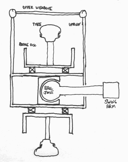
It works out as basically the same as the original Difazio but with the rather complex centre tube and bearing assembly replaced by a simple tube with a balljoint inside connected to the axle, and it also involves several fewer rolling-element bearings than my idea (my wheel attitude control upright is double-sided, I've just drawn it single-sided for reduced clutter). It also eliminates the conical wobble movement on the spherical element with the steering deflected. A boggo car suspension balljoint could be used for the spherical element if a single-sided swingarm was used, or for the somewhat easier case of a double-sided swingarm a double-sided equivalent to the car balljoint is not a massively awkward component either to source or to make out of a car balljoint. Thanks for that!

I really cant tell whats going on there.....as it looks like you want a wobbly wheel bearing ???
anyway.
This is the type of bearing in the strut brace I got for my blower.
http://simplybearings.co.uk/shop/SKF+Bearings-Self...
And ignore the pic on that link, it doesnt look quite like that. The centre section of the bearing can quite easily wobble if required.
better pics.
http://www.bearingboys.co.uk/ourshop/cat_28594-SEL...
Edited by stevieturbo on Saturday 18th August 20:46
Edited by stevieturbo on Saturday 18th August 20:49
stevieturbo said:
I really cant tell whats going on there.....as it looks like you want a wobbly wheel bearing ???
Essentially, yes, and the wheel does not actually wobble because the steering member prevents that.stevieturbo said:
This is the type of bearing in the strut brace I got for my blower.
http://simplybearings.co.uk/shop/SKF+Bearings-Self...
And ignore the pic on that link, it doesnt look quite like that. The centre section of the bearing can quite easily wobble if required.
better pics.
http://www.bearingboys.co.uk/ourshop/cat_28594-SEL...
Those would be ideal if they could handle the amount of wobble I need. Unfortunately they're only specified for 3 degrees at most and many of them are less than that. Doesn't give much steering lock http://simplybearings.co.uk/shop/SKF+Bearings-Self...
And ignore the pic on that link, it doesnt look quite like that. The centre section of the bearing can quite easily wobble if required.
better pics.
http://www.bearingboys.co.uk/ourshop/cat_28594-SEL...
Hence the need for some more complex assembly.Pigeon said:
GreenV8S said:
In that case the spherical joint isn't just moving with the steering, it's actually moving at wheel rotation speed. For a plain bearing with the full weight on it I imagine that would cause problems in terms of rolling resistance and bearing wear.
The spherical joint is indeed rotating at wheel speed, but there is no relative rotational motion between the plain surfaces. Rotation of the wheel is handled by the rolling-element bearing between the spherical joint and the axle. The only relative movement between the spherical surfaces is that due to movement of the steering. (Unless the rolling-element bearing seizes )The above is of course only true in the straight-ahead position; when the steering is turned there will be some relative movement between the spherical surfaces, but not rotational...
Your sketch looks like the sort of thing I was envisaging.
Have you considered attaching the wheel to the axle instead? I mean axle -> cylindrical bearings -> spherical bearing -> swing arm. Attaching to the upper wishbone could be a pain, but this layout would mean the cylindrical bearings are smaller, stronger, cheaper etc. Those big bearings seem like the achilles heel of the original approach.

 @ dilbert
GreenV8S said:
Have you considered attaching the wheel to the axle instead? I mean axle -> cylindrical bearings -> spherical bearing -> swing arm. Attaching to the upper wishbone could be a pain, but this layout would mean the cylindrical bearings are smaller, stronger, cheaper etc. Those big bearings seem like the achilles heel of the original approach.
Now it's me who's having trouble visualising what you're on about. It sounds a bit as if it's only applicable to a single-sided swingarm, whereas my second sketch could be made double-sided with a different spherical joint and that's what I'd really be after doing.Gassing Station | Engines & Drivetrain | Top of Page | What's New | My Stuff