Electronics repair specialist for my ignition?
Discussion


Hi all,
I have one of these gizmos on my car.
http://www.msdignition.com/product.aspx?id=5805
After much diagnosis by an auto electrician we discovered it had failed. It was sent back to the US where they found two faults and repaired them but the process cost me about £200. Got the unit back and the car ran for about 5 mins before first losing one clyinder and then failing all together again.
Fortunately having just had the car tested I know it can only be the box again, not sure what was done wrong could be very simple to fix but it is too costly and too much hassle to ship it all the way back to the US to fix again. It's only a simple amplifier that boosts the signal so cant be that complicated! Where can I get it sorted local to Northampton or does anyone here have the knowledge to fix it for me? I would prefer to have someone who will take a little time and do it right than a big ship of and repair production line type company.
Regards,
Ben
Unfortuately thats not an ignition amp, but a "CD" or capacitor discharge type of trigger. If you can get hold of a circuit diagram, there is a good chance it can be fixed locally, but why do you have one fitted, are you running a single coil on a high rev'ing v8 (or v12), or specilist fuels? Not worth the effort otherwise, a conventional system will work just as well.
Unfortunately this car was built by the previous owner and I bought it as a finished tuning project. First time I've done this and a great way to save buckets of money on doing it yourself but a mission to figure out exactly what's been done over the past 10 years of development!
I haven't had time yet to fully learn what is going on but the car is running 4 individual on plug coil packs (its a 4cylinder turbo). My worry about removing the unit is mainly due to the fact the car runs a stand alone management system and has been mapped to this unit. It is also possible that it was blowing the spark out as it runs fairly high boost (23.5psi)
I've no idea where to find a wiring diagram unfortunately guess its back to the states. Gutted.
I haven't had time yet to fully learn what is going on but the car is running 4 individual on plug coil packs (its a 4cylinder turbo). My worry about removing the unit is mainly due to the fact the car runs a stand alone management system and has been mapped to this unit. It is also possible that it was blowing the spark out as it runs fairly high boost (23.5psi)
I've no idea where to find a wiring diagram unfortunately
guess its back to the states. Gutted.Running high boost pressures does require a higher HT voltage certainly, but you need to ask why is it failing. If you mess around with HT lead resistances you can get some nasty voltages on the coil primary that can blow up semiconductors, but if the coil packs are on top of the plugs this wont be the case. Its possible that the HT voltage is rising so high if the plug wont ionise under full boost, its causing some sort of breakdown in the coil pack, thats being fed back into the MSD as HT. It would be much the same as leaving the coils unplugged from the spark plugs, as say the plug normally ignites at 15kv, the HT voltage does not rise from this point as the arc burns. Disconnect the plug and the voltage just keeps rising,(within reason) until it can find another path to ground (on a conventional system it peaks at around 35kv). I dont know what sort of voltages are needed at 25 psi boost to ignite the spark, but its worth investigating before you pay for another repair.
I am confused as to why you have both a capacitive ignition trigger system and coil packs (which are inductive) I'm not suprised that the CD box goes bang if it is trying to ram 10A and 400odd volts into an inductor!!
Most modern "high performance" inductive coil packs are quite capable of ionising the spark gap at 2 bar of boost!
Personally, considering how much that box weighs and costs, i'd just file it in the B1N and just put on std coil packs myself!
Most modern "high performance" inductive coil packs are quite capable of ionising the spark gap at 2 bar of boost!
Personally, considering how much that box weighs and costs, i'd just file it in the B1N and just put on std coil packs myself!
OK, having read the instructions for that box it looks like it's another good 'ol bit of american snake oil!
Basically, it retains the std coils, but rather than drive them with 12v (well actually 14.7 odd under charge) it looks like it boosts the primary voltage. Probably all this does is to overheat the coils i suspect! All this "multiple sparks / long spark duration" stuff is pretty much bull to unfortunately! You just need 1, reasonable energy spark at the right time, if your combustion system is sooo fecked to require "relighting" multiple times then it isn't going to make any decent power either.
Personally, i recomend whipping the lid off for a look see, usually with anything like that any damage to components/pcb is obvious as it is switching large voltages /currents.
The second thing i recommend is just getting some normal modern coil packs and using them!
what EMS is the car running?
Im with the above, but I remember when these things first came out (early eighties), you could get away with the high voltage on the coil primary as the charge held in the capacitor was very limited, so it may start at 400 volts, but rapidly dies away, so fast in fact that the wires in the coil primary don't have enough time to heat up and burn out and this is what leads to the very short spark duration. Another major difference is the standard "inductive setup" makes the spark when you disconnect the coil primary, (relaying on the magnetic field held in the coil to produce a high voltage as it collapses) whilst I think the capacitive system does it the other way around, by generating the spark as you apply a high voltage to the coil. You do have to ask one question though- if this system was so good, why has it disappeared from the mainstream use?
Thanks for the link. I will email him. In the meatime this could turn into an interesting thread. Maybe I could swap the system for something better/simpler. At the moment the unit does serve a purpose as the car is a 20 year old 944 turbo and originally ran on a distributor ignition (no individual coils like modern cars).
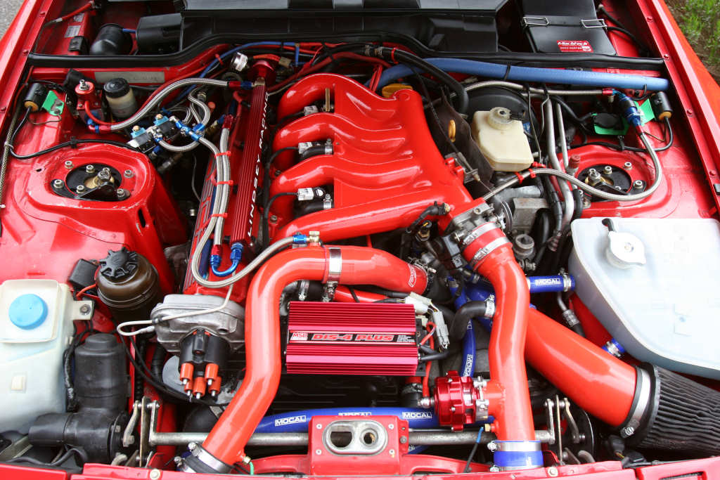
It now feeds a signal to a 'wolf 3D' engine management system, I think its a system pretty specific to 944s (again from the states). That feeds into a J&S knock control system and that goes into the MSD unit which 'boosts' the signal as far as I understand it. I don't know what the voltage into the coils is but I do know the output of the coil was tested at 40kv. This is how the setup looks if its any help:
The car has run with this setup for a fair few years without fault and I drove a 1000 hard miles in the car which was smooth as silk until it randomly refused to start. Which was tracked eventually to the MSD which had all the right signals and supplies going in but zero voltage coming out.
Seeing as you dont actually need this....
The easiest, and cheapest thing to do. Is plug in the bypass plug and just run the coils off the ecu. Or if the ecu cannot fire the coils directly, wire in an amplifier from another car.
Whether it be Bosch, Denso, whatever
As for wiring diagrams etc....google.
The easiest, and cheapest thing to do. Is plug in the bypass plug and just run the coils off the ecu. Or if the ecu cannot fire the coils directly, wire in an amplifier from another car.
Whether it be Bosch, Denso, whatever
As for wiring diagrams etc....google.
stevieturbo said:
Seeing as you dont actually need this....
The easiest, and cheapest thing to do. Is plug in the bypass plug and just run the coils off the ecu. Or if the ecu cannot fire the coils directly, wire in an amplifier from another car.
Whether it be Bosch, Denso, whatever
As for wiring diagrams etc....google.
I like the sound of this idea a lot. I feel much manual reading and a winter project coming on.The easiest, and cheapest thing to do. Is plug in the bypass plug and just run the coils off the ecu. Or if the ecu cannot fire the coils directly, wire in an amplifier from another car.
Whether it be Bosch, Denso, whatever
As for wiring diagrams etc....google.
In answer to the question above of, if its such a good system why isn't it around in the mainstream.. the My Spark Disappeared comment earlier suggests reliability

If you just want a mappable ignition system for not to much money, then the megajolt system is worth a look (brother of the DIY megasquirt fule injection systems).If you like soldering you can build the unit yourself, or you can buy ready built kits from these guys:
http://trigger-wheels.com/store/
You would have to find a sutible method of fitting a trigger wheel to the crank, and mounting the sensor, but the cost involved is pretty reasonable.
http://trigger-wheels.com/store/
You would have to find a sutible method of fitting a trigger wheel to the crank, and mounting the sensor, but the cost involved is pretty reasonable.
er, please tell me the MSD box isn't bolted to the engine???
(typical engine born vibrations on a large capacity 4 cylinder engine can reach an easy 50g, no way will a std pcb/components withstand that without specialist design (check the vibration/temp limits for the device!!)
(I'm not a betting man, but 50p says a large electolytic cap has become disconnected from the pcb )
Edited by anonymous-user on Thursday 9th December 14:04
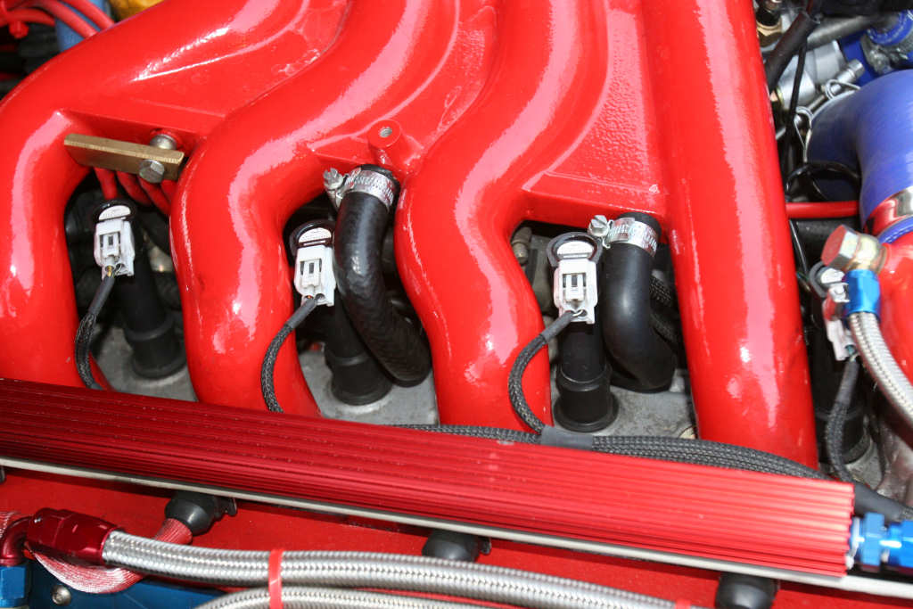
Your pic shows std 2 wire pencil coils, so these are "un-amplified" basic coils. If we assume for now that your ecu does not have a built in amplifier (and only outputs TTL logic signals as a spark trigger) then you can either a) fit modern coils with built in amps, or b) fit std alone ign amplifier (bolted to cooling plate on inner wing (NOT fixed to engine;-)) for each coil.
You will probably have to change the "firing sense" parameter in the ecu to swap from a "ign fires on positive edge" to "ign fires on a negative edge" and also will need to calibrate a suitable "dwell" map to suit your coils (pretty easy with a bit of trial and error and maybe a temp tab or two (or you could do it properly with a current clamp and digital osciloscope).
In the meantime, have a look inside the MSD box and post up some pics if you want some comments on it etc
editted to add:
looking at the physical size (small!) of the coils, i would hazard a guess that these could be too small to provide enough energy for a high boost turbo application in a normal "inductive" layout. (Which might explain why the car has the MSD box fitted!) In which case you either need to engineer in some other larger coils (use amplified coils to make life easy) or just go to a standalone "quad" coil pack and leads etc
Edited by anonymous-user on Thursday 9th December 14:11
Max_Torque said:
er, please tell me the MSD box isn't bolted to the engine???
(typical engine born vibrations on a large capacity 4 cylinder engine can reach an easy 50g, no way will a std pcb/components withstand that without specialist design (check the vibration/temp limits for the device!!)
(I'm not a betting man, but 50p says a large electolytic cap has become disconnected from the pcb )
I think those engines have counter ballance shaft fitted (certaily the later 968 has) but they still vibrate significantly, well spotted!(typical engine born vibrations on a large capacity 4 cylinder engine can reach an easy 50g, no way will a std pcb/components withstand that without specialist design (check the vibration/temp limits for the device!!)
(I'm not a betting man, but 50p says a large electolytic cap has become disconnected from the pcb )
Edited by Max_Torque on Thursday 9th December 14:04
How does the wolf ecu get a crank signal, does it use the stock sensors or is the aftermarket trigger on the cam used? (I couldn't see a sensor fitted there).The answer to your problems is really, get rid of the msd box and fit some sort of oem ignition control but without seeing the wiring setup its tricky to suggest the simplest way of doing this. Of course you could simply revert to the original setup, it will cope with high boost levels, is completely mapable, has knock control built in. If you want to ditch the afm you could fit a lindsay maf kit (although the afm won't really be a restriction). I have worked on & driven a few 400+bhp 944's & they are quite happy running on the standard management.
To the 944 chap, good knowlegde. We must have bumped into each other somewhere over the years if you've been around quick 944s. I know you can run 400hp with the standard ecu but the car is beautfully set up and has been running (as you can probably tell from the unusually high boost) a very healthy 400hp for many years reliably. I really don't want to mess with it too much.
That said, it has been mentioned before that the MSD is in a stupid place and its probably been lucky to only fail twice in that time. It would be nice to replace it with a better solution. To the chap above who mentioned using powered coils, could you tell me a little more about what the ECU would need to provide? I've looked on their website (below) but all it seems to say is '8 sequential ignition outputs'
http://wolfems.cart.net.au/details/635751.html
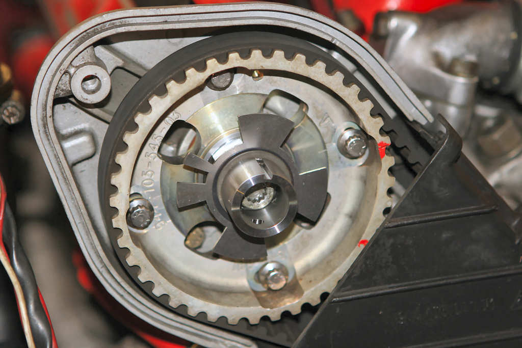
The ecu reads off its own aftermarket crank sensor and the cam sensor (which works from the timing disk you see in the first pic) you can just see the white wire coming out by the side of the distributor in the engine bay pic.
That said, it has been mentioned before that the MSD is in a stupid place and its probably been lucky to only fail twice in that time. It would be nice to replace it with a better solution. To the chap above who mentioned using powered coils, could you tell me a little more about what the ECU would need to provide? I've looked on their website (below) but all it seems to say is '8 sequential ignition outputs'
http://wolfems.cart.net.au/details/635751.html
The ecu reads off its own aftermarket crank sensor and the cam sensor (which works from the timing disk you see in the first pic) you can just see the white wire coming out by the side of the distributor in the engine bay pic.
Reading the installation manual for the V500 EMS shows that the ignition outputs from the ecu are low current high side (8v out) drive. This means they cannot directly fire an inductive ignition coil. They effectively just output a "trigger" signal (low current low voltage) to the coil amplifier (called the "igniter" in the Wolf manual). This amplifier then controls the switching of the actual coil current.
For you application, you will therefor have to either use coil packs that have a built in "amplifier" (these typically have 3 wire connections (+ve, gnd, trigger)) or use a std alone amplifer module to drive either individual coils or a coil pack;
(you will also have to calibrate the dwell time for the coil pack charging, as this i suspect is controlled by the MSD box with the current layout. (dwell is the time for which you allow current to flow into the coil pack before cutting it off (the spark fires as the magnetic field collapses on the switch off) Typical values are in the order of 3 to 8 ms (depending on battV & coil size))
typical ign amp

typical coil pack with built in amplifier

typical coil pack (without amp)

I have a set of amplified high power bosch coil packs in my shed if you want to try them for size!
For you application, you will therefor have to either use coil packs that have a built in "amplifier" (these typically have 3 wire connections (+ve, gnd, trigger)) or use a std alone amplifer module to drive either individual coils or a coil pack;
(you will also have to calibrate the dwell time for the coil pack charging, as this i suspect is controlled by the MSD box with the current layout. (dwell is the time for which you allow current to flow into the coil pack before cutting it off (the spark fires as the magnetic field collapses on the switch off) Typical values are in the order of 3 to 8 ms (depending on battV & coil size))
typical ign amp
typical coil pack with built in amplifier
typical coil pack (without amp)
I have a set of amplified high power bosch coil packs in my shed if you want to try them for size!
Edited by anonymous-user on Friday 10th December 14:07
Yes, we may have bumped into eachother at some point although I've never had the pleasure of seeing your 'new' car. I've been doing more thinking.
There is very limited info on what the ignition output is from the wolf3d. If its a single wire & output per 180* then the easiest solution would be to use a standard amplifier connected to a standard distributor & coil - however the cam sensor would probably have to go.
If it has 2 wires & outputs every 180* it may be possible to use a dual amplifier and a wasted spark coilpack, like this - http://ptm2.cc.utu.fi/~ptmusta/kuvat/MP/Technics/I...
This would be a simple & reliable alternative.
Gassing Station | Engines & Drivetrain | Top of Page | What's New | My Stuff