intake design principles
Discussion


I have been working on a project car for a while, solving various issues as I go.
I have issues with fitment with the intake manifold, I have several options here but, they are all a make do solution.
I am looking into making my own custom intake, have learned a lot and have started playing around with some designs, flow simulations and learning as I go.
I have been using chatGPT to help with some of the design ideas along side bits of research and info around the internet.
the things I have learnt so far
equal length intake runners.
runner length
tapered intake runners - helps with air velocity
bellmouth intake runners - helps guid the air smoothly into the runners
keep the intake runner enterances off the plennum wall
plenum to be 2.5x to 3x the engine capacity.
dont have the throttle body facing directly at the runner enterances - this acts more like a funnel (took me a while to figure this one out)
equal flow rate between runners
avoid pressure drops and dead zones.
taper the plenum going away from the throttle body to help keep pressure
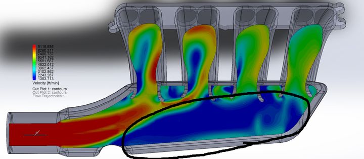
I am designing a D type intake, with the throttle body at on end, in most of my recent deigns, accounting for not blowing directly down the runner ports, keep getting a return vortex, the intake blow hits the back, then follows the contour back over the runner openings, reducing flow as you go back towards the front runner port.
I have read about having split plenum, guids, baffles to get even flow, but the vast majority of intakes I have seen (that i can see inside) dont use any of these, they are all rounded hollowed shapes, the designed shapes seem to be the way they are distributed.
has anyone got any research material, examples or advise on how to get even flow all ports?
I have issues with fitment with the intake manifold, I have several options here but, they are all a make do solution.
I am looking into making my own custom intake, have learned a lot and have started playing around with some designs, flow simulations and learning as I go.
I have been using chatGPT to help with some of the design ideas along side bits of research and info around the internet.
the things I have learnt so far
equal length intake runners.
runner length
tapered intake runners - helps with air velocity
bellmouth intake runners - helps guid the air smoothly into the runners
keep the intake runner enterances off the plennum wall
plenum to be 2.5x to 3x the engine capacity.
dont have the throttle body facing directly at the runner enterances - this acts more like a funnel (took me a while to figure this one out)
equal flow rate between runners
avoid pressure drops and dead zones.
taper the plenum going away from the throttle body to help keep pressure
I am designing a D type intake, with the throttle body at on end, in most of my recent deigns, accounting for not blowing directly down the runner ports, keep getting a return vortex, the intake blow hits the back, then follows the contour back over the runner openings, reducing flow as you go back towards the front runner port.
I have read about having split plenum, guids, baffles to get even flow, but the vast majority of intakes I have seen (that i can see inside) dont use any of these, they are all rounded hollowed shapes, the designed shapes seem to be the way they are distributed.
has anyone got any research material, examples or advise on how to get even flow all ports?
I have been working on this non stop for weeks (outside of working and sleeping)
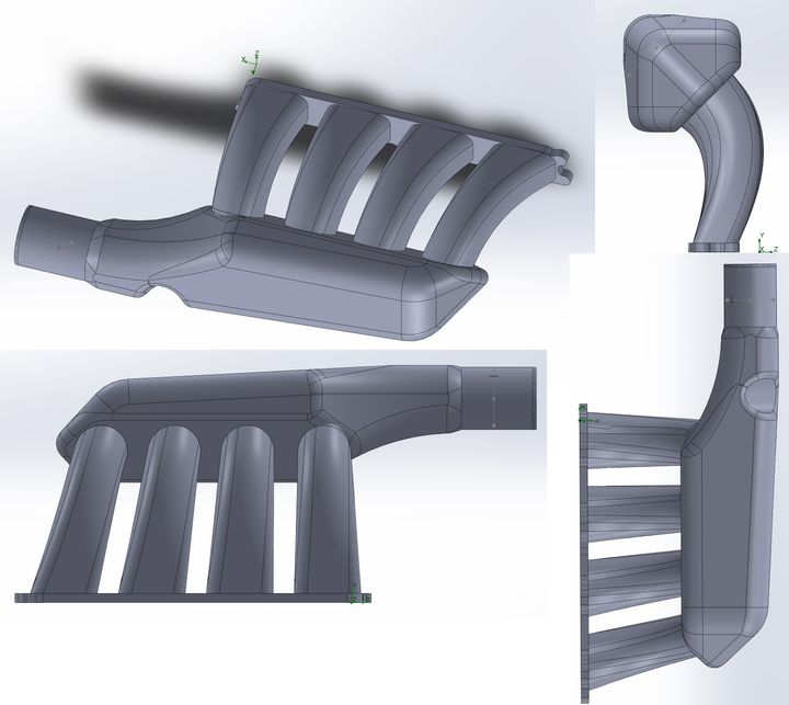
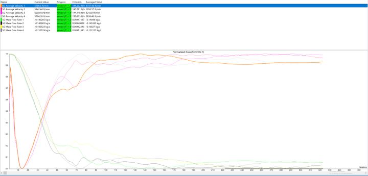
I have designed this around package constraints, space etc, its not my final design as I still need to add map, vac, CVP port etc, however last night I finally got a good result with simulation at less than 10% variation under boost conditions (still got more testing of different scenarios to do, have a test matrix planned)
the goal is to have a healthy running engine for everyday use, so main goal is even flow, secondary goal, make sure it fits!, 3rd goal tuning for low/mid range - its a daily driver for a little fun.
this is the 3rd design I have been through, this time using the principle of subtractive space as the first 2 designs and itterations kept getting package issues when adapting it to try and make them work
so, started with the max amount of space and cut away for the design
I tried to upload an animated gif of of the flow cross section but that didnt work so I have created a video that shows cross section animation and flow trajectories
https://youtu.be/1rRUJaHmAJY
One question I do have is there is a vortex and low pressure to the side of the baffle, without that I am finding it difficult to get equal flow, but then does this mean the plenum space is not being utilised? as mentioned I have used different AI chats for advise (finding anything relating to intake design I have found far and few between, a couple of really good forum posts here and there but finding it difficult to relate to my design) but they generaly point to vortexes under utilising plenum volume and air stagnation.
Edited by element118 on Sunday 20th April 15:12
Edited by element118 on Sunday 20th April 16:41
I’m a little drunk so please forgive me.
I don’t know how you design stuff like this on computer I’d really like to know as I’d like to design an inlet manifold for my car but I think I’m left to actually trial and error over computer testing.
If you look up Swedish plenums vs bluesprint v rs500 manifolds it should bring up loads of post about cosworths discussing manifold designs and also real world dyno comparisons that happened in early 2000’s.
If I had to explain the design basically -
the bluesprint manifold had a pressurised cone that reduced in size behind the throttle body and that connected and fed into a smaller cover over the runner trumpets.
The rs500 had a pressurised elbow that fed the inlet runners.
And the Swedish was just s t for throttle response.
I don’t know how you design stuff like this on computer I’d really like to know as I’d like to design an inlet manifold for my car but I think I’m left to actually trial and error over computer testing.
If you look up Swedish plenums vs bluesprint v rs500 manifolds it should bring up loads of post about cosworths discussing manifold designs and also real world dyno comparisons that happened in early 2000’s.
If I had to explain the design basically -
the bluesprint manifold had a pressurised cone that reduced in size behind the throttle body and that connected and fed into a smaller cover over the runner trumpets.
The rs500 had a pressurised elbow that fed the inlet runners.
And the Swedish was just s
t for throttle response. the design looks a bit off.
normally the runner size at the flange is smaller than the size at the plenum as you build in a little bit of taper. This looks the opposite
Also the inlet of the plenum looks barely any bigger than the outlet of each runner so the velocity into the plenum will be relatively too high
also what are the boundary conditons of the CFD at the inlet and outlet?
Note that each runner is not flowing at the same time due to the firing order and spacing so the robbing (uneven flow in each runner) is nothing like what is predicted.
Inline__engine said:
Note that each runner is not flowing at the same time due to the firing order and spacing so the robbing (uneven flow in each runner) is nothing like what is predicted.
I was aware of that... but had forgotton, so thank you for reminding me of this, my plan was to setup a time based simulation but wanted to get the basics down first as I would asume this would give me a close to what I need? could be completely wrong here, I have read about the waves interfearing with other runners in some types of intakesas to your other point about the runners, you bring upsomething someone else mentioned so made a quick render to show the runners, due to space, they change shape, going from wide and short at the head to narrow and tall in the plenum, the cross section area is actually about 10% bigger at the plenum, the bellmouth then wider than that, this was done because I have a narrow space to fit the intake before hitting the firewall, also with the suggestion (from chat gpt) to keep space between the bellmouth enterances, I have listed full area dimensions below
with regards to your question about boundary conditions, I have used a WOT figure at full boost for this initial testing, inlet is set to 33.2 PSI and the outlet is set to 32.6 PSI, which would be atmosphere + about 18-19 psi.
your could absolutely be correct about the throttle body/plenum inlet vs runner outlet, I will break down the areas to get a better idea of whats going on
throttle body its set to 60mm (3631mm2).
the bellmouth enterance is an elipse at 94mm x 68 mm (5020mm2).
the runner enterance just past the bellmouth is an elipse at 72mm x 49mm (2799mm2).
the runner to head area is shaped to match the port but the area here is 2361mm2.
so the difference between plenum inlet and each runner outlet is approx 1.5x area difference (this I dont actualy know what the relationship should be), from what I can tell from all the simulations is flow into the plenum is fast and its the main thing I have been battling as it just flowed straight down to the end of the plenum and for my first 2 designs completely skipped the 2 runners nearest the throttle body.
From those designs I extended the neck that attaches to the throttle body into the larger plenum area to accomplish a better transition (might adjust this to shorten it down if I can later on) and then adding the baffle, this got me to the current flow rates
Forums | Engines & Drivetrain | Top of Page | What's New | My Stuff