
Discussion


Evening all!
Well I've finally managed to make a start on getting bluey back on the road!

First job on the list was to replace the radiator, the previous owner had done some sort of bodge job on the bleed screw with some liquid metal stuff! Anyhoo found a replacement on eBay a while back and plopped it in. The replacement rad however has plastic sides, not metal as the original did. Does this matter? Same applies for the bleed plug.
However upon removing the old rad I found some rather lovely looking wiring work:

I presume that the 4 connectors taped together are the positive and negative for both fans? I found them underneath the old radiator.
Also noticed that the connectors on the otter switch are missing so I am assuming that the previous owner installed some sort of fan override switch. I did find a toggle switch near the ignition barrel.

So my question is this. Does anyone have any sort of wiring diagram as to how the cooling fans should work? I would prefer to have this automatic as I've no doubt I'll forget to switch the fans on that one time that will make it go pop! Not sure if it makes a difference, but mine in carb, not EFI.
Thanks all!
Kev
Well I've finally managed to make a start on getting bluey back on the road!
First job on the list was to replace the radiator, the previous owner had done some sort of bodge job on the bleed screw with some liquid metal stuff! Anyhoo found a replacement on eBay a while back and plopped it in. The replacement rad however has plastic sides, not metal as the original did. Does this matter? Same applies for the bleed plug.
However upon removing the old rad I found some rather lovely looking wiring work:
I presume that the 4 connectors taped together are the positive and negative for both fans? I found them underneath the old radiator.
Also noticed that the connectors on the otter switch are missing so I am assuming that the previous owner installed some sort of fan override switch. I did find a toggle switch near the ignition barrel.
So my question is this. Does anyone have any sort of wiring diagram as to how the cooling fans should work? I would prefer to have this automatic as I've no doubt I'll forget to switch the fans on that one time that will make it go pop! Not sure if it makes a difference, but mine in carb, not EFI.
Thanks all!
Kev
My guess would be that the 2 otter switch connections have been extended and re routed into the cabin to the switch, you may find the cables near the old location as they would have used connectors or similar to extend.
The diagrams are below, not the best but may help.
http://www.pistonheads.com/Gassing/topic.asp?h=0&a...
The diagrams are below, not the best but may help.
http://www.pistonheads.com/Gassing/topic.asp?h=0&a...
spikep said:
Is the otter switch not on the Swerl pot?
Yes that is an otter switch on the swirl pot, but you could well have one on the radiator as well - normally top left hand side, on the rear face.Mine has both.
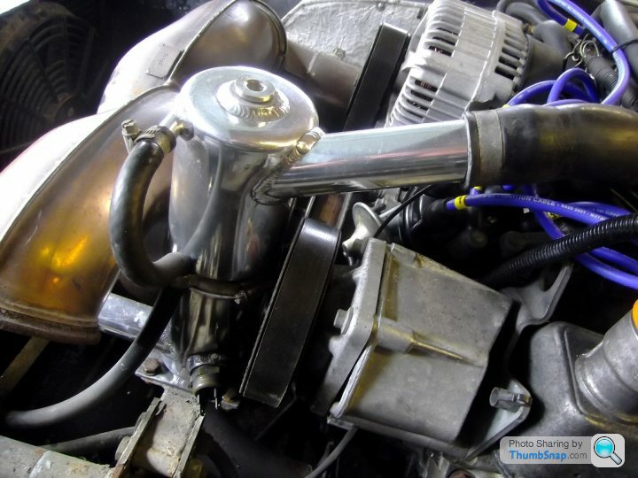
on the swirl pot/header tank. this is redundant.

And on the radiator - LH side just below the rad inlet - you can just make out the terminals.
The early cars, like your M reg one, had the otter switch on the swirl pot, the later cars had it on the radiator. 30mm socket required to remove/install.
My later car has two white two pin in-line connectors, one for each fan, lying under the radiator, and the circuit is switched on and off by the otter switch.
It is ignition wired, so the fans turn off the moment you turn the ignition key off. As simple as that.
Hope I am not re-stating something already said.
My later car has two white two pin in-line connectors, one for each fan, lying under the radiator, and the circuit is switched on and off by the otter switch.
It is ignition wired, so the fans turn off the moment you turn the ignition key off. As simple as that.
Hope I am not re-stating something already said.
Thanks for the info chaps, looks like I've a bit more digging around to do as I've now found a collection of loose wires under the steering column.
I think something spilled onto the side of the swirl pot a long time ago and is just a bit crusty now. My main plan is to get the car back together to make sure it works, get it through a MOT to make sure it's legal, then start working on making bits shiny and generally more presentable!
Just to give you an idea of what I mean, the HT leads are cable tied together at the moment, which I'm pretty sure is not the best thing for them!
I think something spilled onto the side of the swirl pot a long time ago and is just a bit crusty now. My main plan is to get the car back together to make sure it works, get it through a MOT to make sure it's legal, then start working on making bits shiny and generally more presentable!
Just to give you an idea of what I mean, the HT leads are cable tied together at the moment, which I'm pretty sure is not the best thing for them!
Evening all!
Finally managed to make some headway on this. Have now found out that the little black switch on the ignition barrel cover is wired into the alarm so god only know what that does! The only issue it that I'm back at square one
So I think what I would ideally like to do at this point is re-wire the otter switch back in. I'll probably try and put new wiring in as I have no idea what is where at this point. If anybody has an idiots guide on how to do this I'd be very grateful!!
Kev
Finally managed to make some headway on this. Have now found out that the little black switch on the ignition barrel cover is wired into the alarm so god only know what that does! The only issue it that I'm back at square one
So I think what I would ideally like to do at this point is re-wire the otter switch back in. I'll probably try and put new wiring in as I have no idea what is where at this point. If anybody has an idiots guide on how to do this I'd be very grateful!!
Kev
From memory .....
fan relay is standard 4 pin 85,86,30,87
85 = -ve ground return from otter switch
86 = +12v ignition live
87 = +12 switched feed to fans
30 = +12v fused supply from battery
other connector on otter switch needs to be connected to -ve ground somewhere
some cars have twin fuses/relays for the fans others just the one, if you have two it is just a case of the same wiring to both relays and each switched feed goes to an individual fan.
hope that helps
fan relay is standard 4 pin 85,86,30,87
85 = -ve ground return from otter switch
86 = +12v ignition live
87 = +12 switched feed to fans
30 = +12v fused supply from battery
other connector on otter switch needs to be connected to -ve ground somewhere
some cars have twin fuses/relays for the fans others just the one, if you have two it is just a case of the same wiring to both relays and each switched feed goes to an individual fan.
hope that helps

Gassing Station | Chimaera | Top of Page | What's New | My Stuff