New owner - Speedo & wiring challenges
Discussion


Just bought a Feb '92 4.0, and not quite as good as described. It has a couple of issues that maybe some of you can help on.
1) Speedo - It appears to read half speed, ie reads 20mph when doing about 40mph (using phone speedometer app). The LT77 gearbox in this car is supposedly fitted with an 8 pulse speedo driver. Would it read like this if it should be fitted with a 4 pulse speedo drive? The speedo pointer rotates smoothly, no jumping etc. Odometer works, but I haven't checked its accuracy yet. I understand the nylon drive gear in the speedo drive comes in different colours for different teeth counts. What colour should it be on an early pre-cat? Were there 4 and 8 pulse calibrated speedos?
2) Gauges - All the dash gauges only work when the sidelights and instrument backlights are turned on. They all read correctly when on. The wiring shows evidence of previous aftermarket alarms, locking systems being fitted. Perhaps someone wired it this way, but if not, could something in the circuits cause this to happen? I am just looking for somewhere to start. Also the passenger window has stopped working, the door mirrors don't work and the wipers are a work in progress.
I have a copy of the Steve Heath Bible (blue cover edition). I am mechanically minded but electrics are my Achilles heel in the automotive world.
The gauges should be powered from a ignition fused green wire
https://docs.google.com/file/d/0B0yMUb3AgsY4Q0dKTk...
If you can post what you have checked at the window and door mirrors I will gladly attempt to help you solve these problems
https://docs.google.com/file/d/0B0yMUb3AgsY4Q0dKTk...
If you can post what you have checked at the window and door mirrors I will gladly attempt to help you solve these problems
Penelope Stopit said:
The gauges should be powered from a ignition fused green wire
https://docs.google.com/file/d/0B0yMUb3AgsY4Q0dKTk...
If you can post what you have checked at the window and door mirrors I will gladly attempt to help you solve these problems
"Penelope S" thank you for the reply and the link. https://docs.google.com/file/d/0B0yMUb3AgsY4Q0dKTk...
If you can post what you have checked at the window and door mirrors I will gladly attempt to help you solve these problems
Passenger Window
OK, lets start with the passenger window. Last night I removed the centre console and found a black (earth?) wire disconnected from the passenger window switch. Hoping that is the problem, although I haven't put it all back together yet. I did disconnect the connector behind the passenger door speaker for the window motor and put a direct 12v from a battery with jumper wires to the two wires on the window motor plug, but got nothing. The window is currently up.
Door Mirrors
When I got the car, all the wires to the left/right switch for the mirrors were disconnected. The joystick wires are all in place. I am not sure what wire goes to which connector on the back of the switch. See photo.
Misc connectors etc
I could also do with some help identifying the some connectors that seem unused.
Note : Someone has clearly been hacking into some of the wiring and I think its mostly related to aftermarket alarms, remote locking and maybe immobilisers. Some of it isn't pretty. I have an electrician friend coming over to assess things today. The car appears to be a Jan, early Feb '92 build. For example, the boot solenoid releases by pressing the button and the key is not needed in the ignition.

geeman, as yours is a very early car first check your chassis number (see links), as it looks like you have a 4-pulse transducer coupled to an 8-pulse speedo. The TVR Parts department seems to be your best bet to source an 8-pulse variant - not cheap though:
https://tvr-parts.com/tvr-parts/part-details/tvr-f...
https://tvr-parts.com/tvr-parts/part-details/tvr-f...
Unfortunately, the circuit schematics in the 'bible' do not include the dashboard, so it's a dash out and multi-meter time I'm afraid.
https://tvr-parts.com/tvr-parts/part-details/tvr-f...
https://tvr-parts.com/tvr-parts/part-details/tvr-f...
Unfortunately, the circuit schematics in the 'bible' do not include the dashboard, so it's a dash out and multi-meter time I'm afraid.
davep said:
geeman, as yours is a very early car first check your chassis number (see links), as it looks like you have a 4-pulse transducer coupled to an 8-pulse speedo. The TVR Parts department seems to be your best bet to source an 8-pulse variant - not cheap though:
https://tvr-parts.com/tvr-parts/part-details/tvr-f...
https://tvr-parts.com/tvr-parts/part-details/tvr-f...
Unfortunately, the circuit schematics in the 'bible' do not include the dashboard, so it's a dash out and multi-meter time I'm afraid.
Interesting. The car was supposedly fitted with an 8 pulse transducer. I guess I'll have to remove it and check. I think I read you can tell by the part number stamped on it??https://tvr-parts.com/tvr-parts/part-details/tvr-f...
https://tvr-parts.com/tvr-parts/part-details/tvr-f...
Unfortunately, the circuit schematics in the 'bible' do not include the dashboard, so it's a dash out and multi-meter time I'm afraid.


geeman237 said:
davep said:
geeman, as yours is a very early car first check your chassis number (see links), as it looks like you have a 4-pulse transducer coupled to an 8-pulse speedo. The TVR Parts department seems to be your best bet to source an 8-pulse variant - not cheap though:
https://tvr-parts.com/tvr-parts/part-details/tvr-f...
https://tvr-parts.com/tvr-parts/part-details/tvr-f...
Unfortunately, the circuit schematics in the 'bible' do not include the dashboard, so it's a dash out and multi-meter time I'm afraid.
Interesting. The car was supposedly fitted with an 8 pulse transducer. I guess I'll have to remove it and check. I think I read you can tell by the part number stamped on it??https://tvr-parts.com/tvr-parts/part-details/tvr-f...
https://tvr-parts.com/tvr-parts/part-details/tvr-f...
Unfortunately, the circuit schematics in the 'bible' do not include the dashboard, so it's a dash out and multi-meter time I'm afraid.
geeman237 said:
Here are some more teasers for you.

This sub-assembly is probably for back-lighting the perspex switch control panel that is mounted to the front of the whale tail cover. The Windows Up/Down and heater controls (Hot/Cold and Screen/Foot well) have tiny light indicators that are back lit via a system of optic cables and spheres. Also see here:
https://www.pistonheads.com/gassing/topic.asp?h=0&...
... and here:
https://www.rimmerbros.co.uk/Item--i-DRC78
Edited by davep on Friday 12th May 09:02
Penelope Stopit said:
The gauges should be powered from a ignition fused green wire
https://docs.google.com/file/d/0B0yMUb3AgsY4Q0dKTk...
If you can post what you have checked at the window and door mirrors I will gladly attempt to help you solve these problems
Errr is this for a 1960's Griffith???? References generators and regulators.....https://docs.google.com/file/d/0B0yMUb3AgsY4Q0dKTk...
If you can post what you have checked at the window and door mirrors I will gladly attempt to help you solve these problems
geeman237 said:
Penelope Stopit said:
The gauges should be powered from a ignition fused green wire
https://docs.google.com/file/d/0B0yMUb3AgsY4Q0dKTk...
If you can post what you have checked at the window and door mirrors I will gladly attempt to help you solve these problems
Errr is this for a 1960's Griffith???? References generators and regulators.....https://docs.google.com/file/d/0B0yMUb3AgsY4Q0dKTk...
If you can post what you have checked at the window and door mirrors I will gladly attempt to help you solve these problems
I am a touch stuck at the moment as I am moving over from Windows to Debian linux and will have to do a bit of work to be able to access one of my NTFS Formatted backup HDD's that I think I have a good diagram stored on
I am almost certain that someone here has a Griffith wiring diagram and if so please post it up as it will save me some time
Will have a go at installing a NTFS Software to Debian Linux right now and then see if i can find the correct diagram
My apologies, I am not on drugs or anything like that, I have just made a mistake because of my change-over from Windows to Debian Linux
Having managed to view one of my NTFS formatted backup HDD's, I can't find the correct diagram for your car, I did find a very old Griffith diagram that matches the one I posted you a Google Docs link to
I think the only Griffith diagram I have is the wrong diagram and I apologise if I have caused you any inconvenience
If you can gain access to a good diagram please post it here If you don't get everything sorted today by your friend
I think the only Griffith diagram I have is the wrong diagram and I apologise if I have caused you any inconvenience
If you can gain access to a good diagram please post it here If you don't get everything sorted today by your friend
davep said:
geeman237 said:
Here are some more teasers for you.
This sub-assembly is probably for back-lighting the perspex switch control panel that is mounted to the front of the whale tale cover. The Windows Up/Down and heater controls (Hot/Cold and Screen/Foot well) have tiny light indicators that are back lit via a system of optic cables and spheres. Also see here:
https://www.pistonheads.com/gassing/topic.asp?h=0&...
... and here, same unit but without the metal case:
https://www.rimmerbros.co.uk/Item--i-DRC78
Steve
Question. Did the early or all Griffiths have an passenger footwell light mounted directly under the glovebox?
My car does but the wiring for it seems a bit add on.
My electrician colleague and I spend the evening checking wires. We found a blown fuse for the dashboard. Haven't put everything back and tested it all yet. Found a wire that jumped the power from the panel lights to the gauges. Power wasn't getting to the gauges because of what appears to be the blown fuse. But why the fuse blew is still unclear and why go to the trouble of the jumper wire and not replace the fuse unless the fuse kept blowing?
With the dash panel completely out of the car we could not get the ignition to power up. Would this be correct if the dash is out? More work to do over the weekend.
geeman237 said:
Here are some more teasers for you.

Hi Gordon. HK-calling. I am almost certain that Connector A is the forward end of the cable assembly for the speed sensor. The bit that Connector A connects to (not visible from your photo) comes off either the diff or prop shaft. This same connector caused me all sorts of issues when, a few months ago, (whilst removing the whale tail to do some carpet dyeing) I inadvertently disconnected it from its counterpart. This disconnection caused the car to stall at junctions (i.e. when I came off the gas - as the Americans call it - and went into neutral) because the ECU wasn't then getting a signal as to what RPM the car ought to idle at.
This is the aft end of the sensor set up ... https://tvr-parts.com/tvr-parts/part-details/tvr-m...
To access the area where the speed sensor sits on the diff is a bugger to get to. Some people have drilled an access hole in the parcel shelf, so that they can just put their hand/arm directly into the area. Otherwise, you need to find someone with two elbows on one arm ...
Hope that helps!
Terry
You obviously have a number of 'electrics' issues and possible bodges on your car, instead of using guesswork you need to approach it methodically:
Using the schematics on pages 270 -271 of the 'bible' identify the Block connectors to the Fuse/Relay panel. For example, find Block A on the diagram, this has the following pin labels:
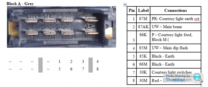
Note down the colour code of the respective wire terminations and trace out the individual connection lines. For example, Block A, pin 7, 30 K is White/Purple, and goes to the Alarm, Courtesy Light Switches and the CDL pin 2.
On the car do continuity checks to verify that the circuit is in accordance with the diagram. Note down any discrepancies and rectify.
Repeat for all Blocks A to S, or the Blocks of interest.
The interconnections from the Blocks to the Relays and Fuses can then be traced through. For example, here is the fuse layout for the 4.x Griffith:

Note the pin labels Upper and Lower and how they tally with the Block pin labels. This helps trace circuit faults where a fuse is involved. Again verify that this is how your car is wired - look out for bodges!
Good luck!
Using the schematics on pages 270 -271 of the 'bible' identify the Block connectors to the Fuse/Relay panel. For example, find Block A on the diagram, this has the following pin labels:
Note down the colour code of the respective wire terminations and trace out the individual connection lines. For example, Block A, pin 7, 30 K is White/Purple, and goes to the Alarm, Courtesy Light Switches and the CDL pin 2.
On the car do continuity checks to verify that the circuit is in accordance with the diagram. Note down any discrepancies and rectify.
Repeat for all Blocks A to S, or the Blocks of interest.
The interconnections from the Blocks to the Relays and Fuses can then be traced through. For example, here is the fuse layout for the 4.x Griffith:
Note the pin labels Upper and Lower and how they tally with the Block pin labels. This helps trace circuit faults where a fuse is involved. Again verify that this is how your car is wired - look out for bodges!
Good luck!
Edited by davep on Monday 15th May 12:29
Dave P, thank you. Where did this information come from????? Great to have. Last night we did release the fuse and relay panel to check some wires. It looks like its not been messed with back there.
When you say block connectors, do you mean the various multi pin connectors in the harness or the blocks at the rear of the fuse/relay panel?
See the attached photo of the red wire with the nasty yellow connector on it. When I removed the dash, this was sitting there, not connected to anything. How do I find out what it’s supposed to connect to? Or does anyone know what it is?
geeman237 said:
Dave P, thank you. Where did this information come from????? Great to have. Last night we did release the fuse and relay panel to check some wires. It looks like its not been messed with back there.
When you say block connectors, do you mean the various multi pin connectors in the harness or the blocks at the rear of the fuse/relay panel?
See the attached photo of the red wire with the nasty yellow connector on it. When I removed the dash, this was sitting there, not connected to anything. How do I find out what it’s supposed to connect to? Or does anyone know what it is?
Nice to see your vehicle has a loom with standard/close on standard British Colour CodingWhen you say block connectors, do you mean the various multi pin connectors in the harness or the blocks at the rear of the fuse/relay panel?
See the attached photo of the red wire with the nasty yellow connector on it. When I removed the dash, this was sitting there, not connected to anything. How do I find out what it’s supposed to connect to? Or does anyone know what it is?
Brown is a unfused battery positive but someone may have used red. Red is a sidelight wire and nothing to be concerned about, red could connect to side/head switch, dash/illumination, that red could be a spare, as long as all the column switches are working correctly you don't need to use it. Make sure to sleeve that red and tie it back safely somewhere or tape it into the loom
Any other colours you are not sure about - post them here
Edited by Penelope Stopit on Friday 12th May 17:30
Gassing Station | Griffith | Top of Page | What's New | My Stuff