
Discussion


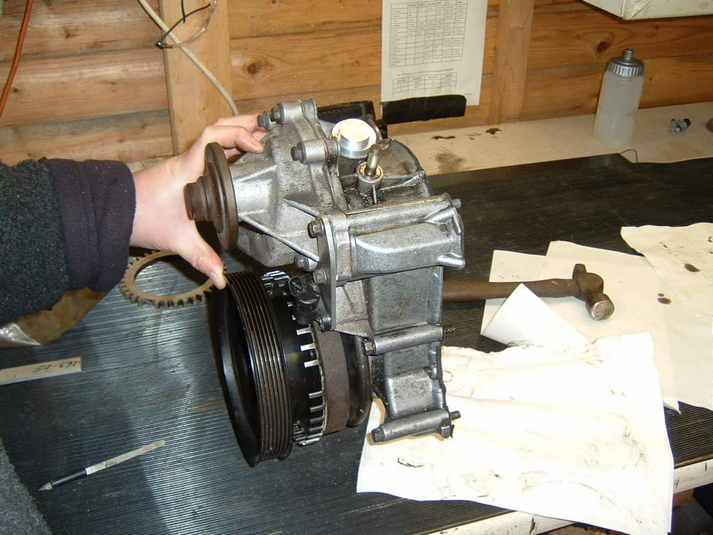
I continue to be a bit puzzled by the serpentine crank pulley. Looking at the car there appears to be three parts, the pulley itself, a fairly substantial part with the timing marks and a few holes drilled (presumably this is the balancing weight) and closest to the engine is a thinner pressed steal part. There is one large bolt in the pulley centre and six smaller bolts.
Question :-
If you undo the centre bolt and remove the pulley does the substantial bit with timing marks come off with it or is it attached to the crank separately. Is it fixed to the pulley with the six smaller bolts ? Presumably there must be a key to locate it all in the correct place on the crank. I have a crank sensor wheel which has six threaded holes that look as if they should match the bolts inside the pulley but can’t quite figure out how it fits unless the plan is to remove the balancing weight.
Please could someone explain.
Question :-
If you undo the centre bolt and remove the pulley does the substantial bit with timing marks come off with it or is it attached to the crank separately. Is it fixed to the pulley with the six smaller bolts ? Presumably there must be a key to locate it all in the correct place on the crank. I have a crank sensor wheel which has six threaded holes that look as if they should match the bolts inside the pulley but can’t quite figure out how it fits unless the plan is to remove the balancing weight.
Please could someone explain.
Centre bolt allows whole assembly to be pulled off. No taper, and it is keyed so should withdraw easily (with removable cross-member out the way).
There are variations on the bits that comprise the damper/pulley, worth a search as there was a recent discussion around this, started by someone who had one thast sounds like yours (there were pics posted). Mt trigger wheel mounted on the six bolts without omitting anything off the OEM assembly but it does sound a bit different. TW is on the rear
There are variations on the bits that comprise the damper/pulley, worth a search as there was a recent discussion around this, started by someone who had one thast sounds like yours (there were pics posted). Mt trigger wheel mounted on the six bolts without omitting anything off the OEM assembly but it does sound a bit different. TW is on the rear
you need to undo the bolts holding the pulley to the large piece first, remove the fan belt pulley, then undo the centre bolt to remove the rest, the big piece is located on a keyway so will go back on in the same position.
I have a crank trigger wheel to fit as well, so be interesting to see replies from people who have done this, is the backing plate discarded and nuts used to fix the bolts in place, ie, assemble on bench and then slide the whole assembly back onto the crankshaft?
I have a crank trigger wheel to fit as well, so be interesting to see replies from people who have done this, is the backing plate discarded and nuts used to fix the bolts in place, ie, assemble on bench and then slide the whole assembly back onto the crankshaft?
Variations above, but I have just done this and had to replace the pulley and add a trigger wheel . . .
The assembly is actually 3 pieces originally by TVR (or at least a lot of the time) If yours is 2 piece, don't worry . . .
TVR balanced their engines by adding/subtracting weight from the whole crank assembly, so flywheel and pulley assemby. The backplate often had a piece of bolt welded to it as a balancing aid.
If you need to replace the harmonic damper on a TVR balanced engine you are in trouble as the damper is specifically balanced to the engine and it is extremely difficult to replicate the balance, read engine out and properly balanced.
Many engines that have been re-built and properly balanced no longer have the back plate as the crank has been balanced along with rods aand pistons . . But not always.
If you undo the crank bolt the whole assembly will come off in one go. You need to remove the chassis cross member. It is much easier to do this than trying to undo the 6 bolts with nuts in situ. If you have a 1/4 drive 13mm socket it is much easier to undo these in place as the bolt heads are right next to the flange, but if all needs to come off, then do it on the bench.
The assembly can only go back together one way, as there is a roll pin in the damper that locates the front pulley.
I needed to replace my damper, and have a new one from John Eales (my engine has been rebuilt and fully balanced). My assembly only had 2 pieces, the front pulley and the damper. The damper had some material removed which was done to make it neutral. John Eales ones come neutral.
The crank bolts is 23mm, or imperial equivalent. Try to use a 6 sided socket as you can easily shag a 12 point one. I borrowed BB's knock gun as suggested and it worked a treat (battery one)
BEWARE - one cautionary note to be aware of. The pulley assembly is locatd to the end of the crank by a woodruff key. If you replace with an assembly that is difficult to get on to the crank, be very careful that it does not disturb the woodruff key. Uing the bolt to pull on the assembly it is not unheard of for the key to be pushed out of it;s slot and then you smas the front cover/oil pump to bits . . .. If it is tight to get on, then put the assembly in hot water to help it fit on the crank.
Good luck Quinny
The assembly is actually 3 pieces originally by TVR (or at least a lot of the time) If yours is 2 piece, don't worry . . .
TVR balanced their engines by adding/subtracting weight from the whole crank assembly, so flywheel and pulley assemby. The backplate often had a piece of bolt welded to it as a balancing aid.
If you need to replace the harmonic damper on a TVR balanced engine you are in trouble as the damper is specifically balanced to the engine and it is extremely difficult to replicate the balance, read engine out and properly balanced.
Many engines that have been re-built and properly balanced no longer have the back plate as the crank has been balanced along with rods aand pistons . . But not always.
If you undo the crank bolt the whole assembly will come off in one go. You need to remove the chassis cross member. It is much easier to do this than trying to undo the 6 bolts with nuts in situ. If you have a 1/4 drive 13mm socket it is much easier to undo these in place as the bolt heads are right next to the flange, but if all needs to come off, then do it on the bench.
The assembly can only go back together one way, as there is a roll pin in the damper that locates the front pulley.
I needed to replace my damper, and have a new one from John Eales (my engine has been rebuilt and fully balanced). My assembly only had 2 pieces, the front pulley and the damper. The damper had some material removed which was done to make it neutral. John Eales ones come neutral.
The crank bolts is 23mm, or imperial equivalent. Try to use a 6 sided socket as you can easily shag a 12 point one. I borrowed BB's knock gun as suggested and it worked a treat (battery one)
BEWARE - one cautionary note to be aware of. The pulley assembly is locatd to the end of the crank by a woodruff key. If you replace with an assembly that is difficult to get on to the crank, be very careful that it does not disturb the woodruff key. Uing the bolt to pull on the assembly it is not unheard of for the key to be pushed out of it;s slot and then you smas the front cover/oil pump to bits . . .. If it is tight to get on, then put the assembly in hot water to help it fit on the crank.
Good luck Quinny
Where did you get the trigger wheel from and is yours a Serp?
I got mine as a part of a kit that came from Emerald. The installation was done by V8D. They looked at it and said this was the wrong trigger wheel. The one Emerald supply is for a pre-Serp only.
When they checked it turned out that the maker Emerald gets them from is working on a Serp kit, but it’s not yet available.
The result was V8D got a J.E. one fitted and balanced to mine.
I got mine as a part of a kit that came from Emerald. The installation was done by V8D. They looked at it and said this was the wrong trigger wheel. The one Emerald supply is for a pre-Serp only.
When they checked it turned out that the maker Emerald gets them from is working on a Serp kit, but it’s not yet available.
The result was V8D got a J.E. one fitted and balanced to mine.
Mine is a John Eales trigger from John Eales 
Clive, you'll have to do what Fester has done. If your back plate has got weight added to it, then you will need to get the assembly re balanced to suit the new trigger wheel. I went for the JE kits as I trust his stuff and I preferred the solidity of it compared to other installations I have seen. That is not a criticism of other kit, just a personal preference.
Key to my decision was the sensor bracket, which means you don't have to fabricate your own, which always looks a right bodge job
Summary - you will have to remove backplate to fit JE trigger wheel, and then you'll have to have the balance checked by V8D or JE.
Clive, you'll have to do what Fester has done. If your back plate has got weight added to it, then you will need to get the assembly re balanced to suit the new trigger wheel. I went for the JE kits as I trust his stuff and I preferred the solidity of it compared to other installations I have seen. That is not a criticism of other kit, just a personal preference.
Key to my decision was the sensor bracket, which means you don't have to fabricate your own, which always looks a right bodge job
Summary - you will have to remove backplate to fit JE trigger wheel, and then you'll have to have the balance checked by V8D or JE.
My idea is to reduce the thickness of the balanced backing plate to 10mm (down from 20mm) by getting it lathed into two discs (resulting in an inside and an outside disc)..then reversing the inside disc and re-welding them. That way the balance stays the same..at it's 10mm thiner allowing a 5mm trigeer wheel and at least one spacer.
Feedback most welcome....
Feedback most welcome....
When I put mine on I also had one of those small balancing weights on the thin back piece - it had 4 bolts on and then the last two were replaced by a small thin balance weight which was tapped to allow the bolts to tighten in to it. I had to bin it though as it wouldn't fit on the back with the trig wheel on but having looked at it, it was so small that its mass would have been almost completely replaced by the two new nuts that replaced it so i'm not too worried about its loss. I'm hoping to have the engine lightened and balanced with low comp pistons in readyness for a charger in the next few months though so i'm sure it'll get sorted then anyway! 
Edited by thenick on Monday 11th February 00:07


thenick said:
When I put mine on I also had one of those small balancing weights on the thin back piece - it had 4 bolts on and then the last two were replaced by a small thin balance weight which was tapped to allow the bolts to tighten in to it. I had to bin it though as it wouldn't fit on the back with the trig wheel on but having looked at it, it was so small that its mass would have been almost completely replaced by the two new nuts that replaced it so i'm not too worried about its loss. I'm hoping to have the engine lightened and balanced with low comp pistons in readyness for a charger in the next few months though so i'm sure it'll get sorted then anyway!
This sounds like mineEdited by thenick on Monday 11th February 00:07
I cant believe the bit that ajoins the two bolts together is anything to do with Balancing is it? Although I guess the bit that has been welded under the lip on the outer edge is..but really is something so small in weight( we must be taking ounce) really going to do anything?
I a guessing you just binned yours nick and then stuck the TW in its place? If that is the case how do you get it rebalanced correctly and what would they do? just welded a small bolt to the side of the trigger wheel?
BB
I'm not sure I can see your problem? Just use longer bolts, then 6 nuts to hold the trigger wheel on. Are you questioning the heights because you want to use spacers? I think the tw is strong enough to be clamped without spacers, and then you have not changed the dynamic balance (apart from the missing tooth) AFI can see.
Dave
Dave
My mates intermediate serp grif 500 looked just like BB's - we didn't want to remove or alter that rear plate, as it looked important to the balance.
So lathed it down and sandwiched in a ford 36-1 wheel between the outer and the damper:
http://www.mez.co.uk/ms11.html
So lathed it down and sandwiched in a ford 36-1 wheel between the outer and the damper:
http://www.mez.co.uk/ms11.html
Edited by eliot on Tuesday 12th February 07:31
Got the pulley assembly off last night and it looks exactly like BB’s , complete with threaded plate and bit of bar welded under the lip, the plate has 1165 stamped on it. Slightly alarming thing is the big bit with timing marks ( the damper ? ) is free to turn on the pulley which rather makes a mockery of worrying about the weight of a couple of bolts. My main concern at the moment is how does the damper fix to the pulley ? So far I have not been able to separate them as there is one bolt that so far has not moved.
It looks as if the rear plate nuts are captive (either that or they are held on with paint ) so to put the trigger wheel behind here with longer bolts would mean taking them off. Putting the trigger wheel in front of the rear plate would require drilling the holes on the trigger wheel to clearance rather than threaded.
It looks as if the rear plate nuts are captive (either that or they are held on with paint ) so to put the trigger wheel behind here with longer bolts would mean taking them off. Putting the trigger wheel in front of the rear plate would require drilling the holes on the trigger wheel to clearance rather than threaded.

spend said:
I'm not sure I can see your problem? Just use longer bolts, then 6 nuts to hold the trigger wheel on. Are you questioning the heights because you want to use spacers? I think the tw is strong enough to be clamped without spacers, and then you have not changed the dynamic balance (apart from the missing tooth) AFI can see.
Dave
I thought about that Dave, but if the trigger wheel has to sit right at the back then it would need spacers as it would sit inside the lip of the balancing wheel. I guess i could move it the other side of it but then maybe the sensor would have to have a spacer made to make it sit out further .Dave
I will take it all apart this eve and see if i can get a good position with all fitted...and maybe try the longer bolt option.
Cheers Spendy and Eliot
BB
Gassing Station | Griffith | Top of Page | What's New | My Stuff