
Legible Griffy Wiring Diagram - Need One
Discussion


Does anyone have a decent wiring Diagram for a Serp 500 that I can actually use, see through my cataracts and follow with my banana like fingers? I've got the diagram in Mr Heath's book but its making my eye-balls bleed! There's gotta be something bigger, better and possibly utilising colour, coz right now I need it.
I'm installing MS2 and the diagrams I have for that are a doddle and the basic looms (x2) are clearly labeled; no problem. The issue lies in the fact that I want to tie in alongside the parts of the old loom that are not redundant so I'll have something bespoke to my needs, neat and functional and not the 'Bunch of B*****ds' that currently exists. Maybe I should just expose all the wiring and tease out what I need (when I can be certain of what that is!). What have others done?
Additionally, I though I'd look at relocating the Ignition and Fuel Pump relays onto the main board instead of them dangling off a limb. The ECU no longer has influence so why not?!
Basically I want to see what's what and connected to where and the diagram I have is barely suitable.
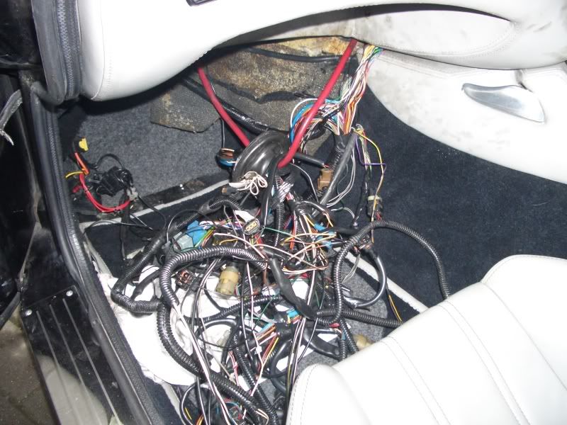
Here's a shot of an afternoons disconnecting, cutting, peeling, pulling and finger stabbing just before the men in white coats arrived after my call to the Samaritans:
I'm installing MS2 and the diagrams I have for that are a doddle and the basic looms (x2) are clearly labeled; no problem. The issue lies in the fact that I want to tie in alongside the parts of the old loom that are not redundant so I'll have something bespoke to my needs, neat and functional and not the 'Bunch of B*****ds' that currently exists. Maybe I should just expose all the wiring and tease out what I need (when I can be certain of what that is!). What have others done?
Additionally, I though I'd look at relocating the Ignition and Fuel Pump relays onto the main board instead of them dangling off a limb. The ECU no longer has influence so why not?!
Basically I want to see what's what and connected to where and the diagram I have is barely suitable.
Here's a shot of an afternoons disconnecting, cutting, peeling, pulling and finger stabbing just before the men in white coats arrived after my call to the Samaritans:
Decide what you need and get someone to make one up for you. It's so much easier. You get rid of the awful TVR engine loom and in my case I got it made so that it's neater, it stays cleaner, it's better protected, it uses aircraft spec wiring, it's less than half the weight, it's got no spurious dead ends, loops, multiplugs you don't need etc etc . . I could specify exactly what I wanted and where I wanted it positioned, how I wanted wire in certain elements. . . Micro relays etc etc . .
I know mines an Emerald install and therefore slightly different, but listening to Dave Walker talking about some of the wiring that comes in with installs and the issues piggy backing onto poor wiring can cause I wanted go another way.. .
I can wield a pair of crimping pliers and a soldering iron with the best of em, but nothing like someone who does it for a living. On TGP I think Simon posted pics of the difference between our new looms and the old ones . .. .
I know mines an Emerald install and therefore slightly different, but listening to Dave Walker talking about some of the wiring that comes in with installs and the issues piggy backing onto poor wiring can cause I wanted go another way.. .
I can wield a pair of crimping pliers and a soldering iron with the best of em, but nothing like someone who does it for a living. On TGP I think Simon posted pics of the difference between our new looms and the old ones . .. .
2Munkys said:
Does anyone have a decent wiring Diagram for a Serp 500 that I can actually use, see through my cataracts and follow with my banana like fingers? I've got the diagram in Mr Heath's book but its making my eye-balls bleed! There's gotta be something bigger, better and possibly utilising colour, coz right now I need it.
I'm installing MS2 and the diagrams I have for that are a doddle and the basic looms (x2) are clearly labeled; no problem. The issue lies in the fact that I want to tie in alongside the parts of the old loom that are not redundant so I'll have something bespoke to my needs, neat and functional and not the 'Bunch of B*****ds' that currently exists. Maybe I should just expose all the wiring and tease out what I need (when I can be certain of what that is!). What have others done?
Additionally, I though I'd look at relocating the Ignition and Fuel Pump relays onto the main board instead of them dangling off a limb. The ECU no longer has influence so why not?!
Basically I want to see what's what and connected to where and the diagram I have is barely suitable.
Here's a shot of an afternoons disconnecting, cutting, peeling, pulling and finger stabbing just before the men in white coats arrived after my call to the Samaritans:
Are you nuts Bruce? I'm installing MS2 and the diagrams I have for that are a doddle and the basic looms (x2) are clearly labeled; no problem. The issue lies in the fact that I want to tie in alongside the parts of the old loom that are not redundant so I'll have something bespoke to my needs, neat and functional and not the 'Bunch of B*****ds' that currently exists. Maybe I should just expose all the wiring and tease out what I need (when I can be certain of what that is!). What have others done?
Additionally, I though I'd look at relocating the Ignition and Fuel Pump relays onto the main board instead of them dangling off a limb. The ECU no longer has influence so why not?!
Basically I want to see what's what and connected to where and the diagram I have is barely suitable.
Here's a shot of an afternoons disconnecting, cutting, peeling, pulling and finger stabbing just before the men in white coats arrived after my call to the Samaritans:
 That looks scary!
shpub said:
Errr I redrew the ECU wiring loom schematic - see page 84 - which is what you need to hook up the MS2 system as it will have access to all the sensors and power.
Yep, I'm familiar with that one Steve and it has been perused, ta. The MS2 side of things isn't the issue but it would appear that the existing loom contains stuff other than ECU input/output and operation. Dependent on what and how much of the 'other stuff' there is will dictate whether or not I inclose it in the new loom or keep it separate (likely). That's why I'm looking for something with a little more clarity .Johno, that new loom is purely to/from the ECU right? Anything else encompassed there in? Doesn't look like it.
I guess you may be getting confused with the peripheral things like the:
Power & Relays
speed sensing
tacho / coil stuff
alarm / immob + inertia switch.
purge valve
1. I'd just link the + / - and ign to your new relays, everything they power up should be part of your new loom.
2. You can ignore and wire the speed sensor direct to you speedo now (no splitter/black box required?)
3. You can remove everything except the single wire from ecu to tacho across dash (with your new tacho). It will now be separate from your coil pack installation.
4. figure that one out as they vary...- a new alarm immob may be a good idea at this time (if you get installation instructions )
)
5. Just link to an ECU output that you choose and connect a relay to ground the purge valve.
Power & Relays
speed sensing
tacho / coil stuff
alarm / immob + inertia switch.
purge valve
1. I'd just link the + / - and ign to your new relays, everything they power up should be part of your new loom.
2. You can ignore and wire the speed sensor direct to you speedo now (no splitter/black box required?)
3. You can remove everything except the single wire from ecu to tacho across dash (with your new tacho). It will now be separate from your coil pack installation.
4. figure that one out as they vary...- a new alarm immob may be a good idea at this time (if you get installation instructions
)5. Just link to an ECU output that you choose and connect a relay to ground the purge valve.
@Johno
Who did the work on your wiring, any indications of cost, and did they move the fuseboard?
I have a Griff with a boot and electrics are my main cause of AA callout. I've been thinking of moving the fuse/relays to the cubby hole and reducing the wiring as much as possible. Any guidance would be very much appreciated.
Who did the work on your wiring, any indications of cost, and did they move the fuseboard?
I have a Griff with a boot and electrics are my main cause of AA callout. I've been thinking of moving the fuse/relays to the cubby hole and reducing the wiring as much as possible. Any guidance would be very much appreciated.
Bruce
It depends on what you want the loom to do.
The loom in the picture is identical to mine (apart from one very subtle difference that was learnt after doing mine - purely aesthetic)
The loom in the shot replaces the engine loom completely. The only additions to it are a shift light, 2 stage cooling with the wiring removed from the back of the fuse box so it could be mated above the glovebox minimising any more wires in the engine bay, wideband sensor (or at least built with a plug to accept a WB) my WB is wired into the n/s wing and threaded into the passenger footwell and above the glove box as well. Coil packs and the facility to run an ICV if I should want too . . . which I've had no need for.

You can see in the picture the relays which hang in the original loom are replaced by the micro relay block you can see. You'll also not the brown and white connector which is where the engine loom connects to the dash loom.
I've never felt the need to move the fusebox.. . . It's in a dry, secure, shielded away area and I don't need to change fuses regularly. If I was having to change fuses on a regular basis then I may consider it, but I'd first be investigating why I was having to change fuses. The 2 stage cooling with the Emerald can be done with extra wiring, but having sufficiently heavy gauge wiring in place to each separately already it seems a no brainer to pull em out of the fuse box and build it into the loom, so I had it made with connector ready to accept the wiring I then re-loomed from the fuse box in the footwell.
As Simon has said, Paul Dove did the looms for us and he's an absolutely top fella. Was full time freelance, but spent some time working for Lotus on a contract and they offered him a job, with the work being a bit hit and miss he's now full time on the Evora production line. He's the only person I let do any electrics to my car other than myself, cos he's such a nice fella, reasonable and local to me.
If you want his contact details then please PM me and I'll give you his email and phone number. With him being local to me (in fact he's got 2 of my books ) if there's a question of routing, length of wiring etc he can use my car to measure up with if need be.
It depends on what you want the loom to do.
The loom in the picture is identical to mine (apart from one very subtle difference that was learnt after doing mine - purely aesthetic)
The loom in the shot replaces the engine loom completely. The only additions to it are a shift light, 2 stage cooling with the wiring removed from the back of the fuse box so it could be mated above the glovebox minimising any more wires in the engine bay, wideband sensor (or at least built with a plug to accept a WB) my WB is wired into the n/s wing and threaded into the passenger footwell and above the glove box as well. Coil packs and the facility to run an ICV if I should want too . . . which I've had no need for.
You can see in the picture the relays which hang in the original loom are replaced by the micro relay block you can see. You'll also not the brown and white connector which is where the engine loom connects to the dash loom.
I've never felt the need to move the fusebox.. . . It's in a dry, secure, shielded away area and I don't need to change fuses regularly. If I was having to change fuses on a regular basis then I may consider it, but I'd first be investigating why I was having to change fuses. The 2 stage cooling with the Emerald can be done with extra wiring, but having sufficiently heavy gauge wiring in place to each separately already it seems a no brainer to pull em out of the fuse box and build it into the loom, so I had it made with connector ready to accept the wiring I then re-loomed from the fuse box in the footwell.
As Simon has said, Paul Dove did the looms for us and he's an absolutely top fella. Was full time freelance, but spent some time working for Lotus on a contract and they offered him a job, with the work being a bit hit and miss he's now full time on the Evora production line. He's the only person I let do any electrics to my car other than myself, cos he's such a nice fella, reasonable and local to me.
If you want his contact details then please PM me and I'll give you his email and phone number. With him being local to me (in fact he's got 2 of my books
) if there's a question of routing, length of wiring etc he can use my car to measure up with if need be.Johno said:
Bruce
It depends on what you want the loom to do.
The loom in the picture is identical to mine (apart from one very subtle difference that was learnt after doing mine - purely aesthetic)
The loom in the shot replaces the engine loom completely. The only additions to it are a shift light, 2 stage cooling with the wiring removed from the back of the fuse box so it could be mated above the glovebox minimising any more wires in the engine bay, wideband sensor (or at least built with a plug to accept a WB) my WB is wired into the n/s wing and threaded into the passenger footwell and above the glove box as well. Coil packs and the facility to run an ICV if I should want too . . . which I've had no need for.
You can see in the picture the relays which hang in the original loom are replaced by the micro relay block you can see. You'll also not the brown and white connector which is where the engine loom connects to the dash loom.
I've never felt the need to move the fusebox.. . . It's in a dry, secure, shielded away area and I don't need to change fuses regularly. If I was having to change fuses on a regular basis then I may consider it, but I'd first be investigating why I was having to change fuses. The 2 stage cooling with the Emerald can be done with extra wiring, but having sufficiently heavy gauge wiring in place to each separately already it seems a no brainer to pull em out of the fuse box and build it into the loom, so I had it made with connector ready to accept the wiring I then re-loomed from the fuse box in the footwell.
As Simon has said, Paul Dove did the looms for us and he's an absolutely top fella. Was full time freelance, but spent some time working for Lotus on a contract and they offered him a job, with the work being a bit hit and miss he's now full time on the Evora production line. He's the only person I let do any electrics to my car other than myself, cos he's such a nice fella, reasonable and local to me.
If you want his contact details then please PM me and I'll give you his email and phone number. With him being local to me (in fact he's got 2 of my books ) if there's a question of routing, length of wiring etc he can use my car to measure up with if need be.
Thanks Mark, and yep, I'm aware of Paul Dove's work.It depends on what you want the loom to do.
The loom in the picture is identical to mine (apart from one very subtle difference that was learnt after doing mine - purely aesthetic)
The loom in the shot replaces the engine loom completely. The only additions to it are a shift light, 2 stage cooling with the wiring removed from the back of the fuse box so it could be mated above the glovebox minimising any more wires in the engine bay, wideband sensor (or at least built with a plug to accept a WB) my WB is wired into the n/s wing and threaded into the passenger footwell and above the glove box as well. Coil packs and the facility to run an ICV if I should want too . . . which I've had no need for.
You can see in the picture the relays which hang in the original loom are replaced by the micro relay block you can see. You'll also not the brown and white connector which is where the engine loom connects to the dash loom.
I've never felt the need to move the fusebox.. . . It's in a dry, secure, shielded away area and I don't need to change fuses regularly. If I was having to change fuses on a regular basis then I may consider it, but I'd first be investigating why I was having to change fuses. The 2 stage cooling with the Emerald can be done with extra wiring, but having sufficiently heavy gauge wiring in place to each separately already it seems a no brainer to pull em out of the fuse box and build it into the loom, so I had it made with connector ready to accept the wiring I then re-loomed from the fuse box in the footwell.
As Simon has said, Paul Dove did the looms for us and he's an absolutely top fella. Was full time freelance, but spent some time working for Lotus on a contract and they offered him a job, with the work being a bit hit and miss he's now full time on the Evora production line. He's the only person I let do any electrics to my car other than myself, cos he's such a nice fella, reasonable and local to me.
If you want his contact details then please PM me and I'll give you his email and phone number. With him being local to me (in fact he's got 2 of my books
) if there's a question of routing, length of wiring etc he can use my car to measure up with if need be.For my MS2 ECU there are two sockets, essentially one for sensory input and one for output. As such it'd be prudent to keep the two bundles seperated but essentially, I'll have what you've depicted. I'm not foreseeing problem with this though (he states over-confidently).
I think there may be space on the main board for two relays and for the sake of neatness and simplicity I could use these for the Ignition and Fuel Pump in conjunction with existing fuse sockets. A small four gang fuse board to be used for the other fusing requirements.
Despite the above, which wasn't the reason for the post, I wanted a decent wiring diagram just for the sake of factoring-in any wiring re-routes, looming, connections etc (I'm keeping the otter switch function for example). I think it's called 'planning ahead' and that's where I am with it right now.
I'll keep you updated.
Gassing Station | Griffith | Top of Page | What's New | My Stuff