Discussion


can someone clear something up for me, i've been looking at this diagram and wanted to know if there's an update or change to later systems (1989 flapper 400)
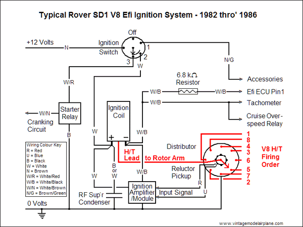
i have 2 wires going to the positive side of the coil (both white/yellow) and one to the negative (white/black). 1 w/y comes from a 3 pin multiplug that goes to the back of the rev counter and the other connects to the ignition module, the w/b goes back from module to coil and ECU, the second bit i understand as this is how the high tension is generated but according to the diag the rev counter gets its feed from the negiative side??
why does mine use the positive side for revs? The 3 pin plug at the back of the rev counter has 2 w/y wires and 1 white (with red band), as far as i can tell 1 w/y goes to coil and the other 2 wires go across to the passenger side and join into a 5 pin connector, between these 2 plugs is where i seem to be getting some resistance in the wiring but i can't see how the wires are connected to each other and i can't get my head aroun which wire could be at fault if at all or am i getting mixed up with other parts of the system!!! i'm sure this doesn't make any sense when put into writing but i'm trying to find out why i'm only get 9/10 volts at coil when cranking and initial start up until i raise the revs.
am i right in thinking that power for ignition would have to go through the steering relay and could this cause a drop in voltage, can it be tested?
The only way thre would be pulses for the tacho to read on the +ve side of the coil is if you have some ballast resistance in the wiring (it might be built into the harness).
The the +ve side will go up and down each time the ignition amplifier grounds the -ve side.
To test this, disconnect the coil +, then turn on the ignition, and measure the resistance from the coil + wire you just took off, to battery +. It might be around 6 to 20 ohms or so (depending what coil it was meant to drop voltage for).
If this is the case, this is why your coil + never gets to the full 13.5V nominal.
Actually if it's a 400SE flapper then you are correct the diagram is wrong however it may depend on the type of instruments you have fitted.
My 400 had the tacho in the COIL +ve feed (erasy to check when you unplug the tach 3 pin plug the car won't start) in the back of the tacho was a transformer that was sensing the Current pulses being caused by the coil being switched on and off by the dizzy. I have since modified the unit to use a conventional voltage pulse (easy mod just bypassed the current sensing transformer !) as it's driven by megajolt now.
My 400 had the tacho in the COIL +ve feed (erasy to check when you unplug the tach 3 pin plug the car won't start) in the back of the tacho was a transformer that was sensing the Current pulses being caused by the coil being switched on and off by the dizzy. I have since modified the unit to use a conventional voltage pulse (easy mod just bypassed the current sensing transformer !) as it's driven by megajolt now.
will have a look cheers adam, so if it does read resistance are you saying that its not supposed to get 12v and above? my only other thought was could the alternator be causing the problem as i always show low voltage when i first start the car hot/cold until the revs are raised and then everything goes back to normal and always get a health 14volts, just seems odd that the problem only exists for a short period at start up!!!
yes same as yours then simon, if you disconnect plug to rev counter she won't start! should i have a third wire from the +ve side of the coil goig to earth?
yes same as yours then simon, if you disconnect plug to rev counter she won't start! should i have a third wire from the +ve side of the coil goig to earth?
Edited by al 350i on Tuesday 5th March 18:23
my rev counter packed up and the car would not start !if you un plug the rev counther and join up the yellow and white wires the car will run ! wire goes from rev counter to coil then to distributor !
al 350i said:
will have a look cheers adam, so if it does read resistance are you saying that its not supposed to get 12v and above? my only other thought was could the alternator be causing the problem as i always show low voltage when i first start the car hot/cold until the revs are raised and then everything goes back to normal and always get a health 14volts, just seems odd that the problem only exists for a short period at start up!!!
yes same as yours then simon, if you disconnect plug to rev counter she won't start! should i have a third wire from the +ve side of the coil goig to earth?
yes same as yours then simon, if you disconnect plug to rev counter she won't start! should i have a third wire from the +ve side of the coil goig to earth?
Edited by al 350i on Tuesday 5th March 18:23
Al 350i, FYI, Just copied the following list from the British (1983) Wiring Colour Code Table:
White - Ignition switch or starter solenoid to ballast resistor
White Brown - Oil pressure switch to warning light or gauge, or starter relay to oil pressure switch
White Blue - Choke switch to choke solenoid (unfused) and/or choke to switch to warning light, or electronic ignition distributor to drive resistor
White Red - Starter switch to starter solenoid or inhibitor switch or starter relay or ignition (start position) to bulb failure unit
White Purple - Fuel pump no 1 or right-hand to changeover switch
White Green - Fuel pump no 2 or left-hand to changeover switch
White Light green - Start switch to starter interlock or oil pressure switch to fuel pump or start inhibitor switch to starter relay or solenoid
White Yellow - Ballast resistor to coil or starter solenoid to coil
White Black - Ignition coil contact breaker to distributor contact breaker, or distributor side of coil to voltage impulse tachometer
White Pink - Ignition switch to radio fuse
White Slate - Current tachometer to ignition coil
White Orange - Hazard warning lead to switch
You'll see that White Yellow is used for Ballast Resistor to Coil and/or starter solenoid to coil.
So Adam's Explanation regarding Ballast resistor is correct
Note also that a white wire is used for Ignition switch or starter solenoid to ballast resistor
So the 1982 - 6 ignition diagram can be imagined to contain a ballast resistor between the Ignition switch and Coil positive. Using the White yellow wires as indicated by the OP.
Indeed the diagram could easily be used to redraw the system on your car by tracing the wires, and where they go.
For further help regarding wiring colours see the full table here:
http://www.dimebank.com/tech/LucasColours.html
al 350i said:
will have a look cheers adam, so if it does read resistance are you saying that its not supposed to get 12v and above? my only other thought was could the alternator be causing the problem as i always show low voltage when i first start the car hot/cold until the revs are raised and then everything goes back to normal and always get a health 14volts, just seems odd that the problem only exists for a short period at start up!!!
yes same as yours then simon, if you disconnect plug to rev counter she won't start! should i have a third wire from the +ve side of the coil goig to earth?
Hi Al, from memory (most of this is now in a junk box in the garage...) you should have two wires at the coil+, one will be the supply via the tacho and the second will be the positive supply to the ignition module (there may be a 3rd if you have a RF suppressor) the - connection should have the other wire from the ignition module and also the trigger wire for the injection. yes same as yours then simon, if you disconnect plug to rev counter she won't start! should i have a third wire from the +ve side of the coil goig to earth?
Edited by al 350i on Tuesday 5th March 18:23
I'm not sure any British car actually followed the colour codes, I know a lot of the TVR loom does not, A DVM is a better bet !
honestjohntoo said:
Al 350i, FYI, Just copied the following list from the British (1983) Wiring Colour Code Table:
White - Ignition switch or starter solenoid to ballast resistor
White Brown - Oil pressure switch to warning light or gauge, or starter relay to oil pressure switch
White Blue - Choke switch to choke solenoid (unfused) and/or choke to switch to warning light, or electronic ignition distributor to drive resistor
White Red - Starter switch to starter solenoid or inhibitor switch or starter relay or ignition (start position) to bulb failure unit
White Purple - Fuel pump no 1 or right-hand to changeover switch
White Green - Fuel pump no 2 or left-hand to changeover switch
White Light green - Start switch to starter interlock or oil pressure switch to fuel pump or start inhibitor switch to starter relay or solenoid
White Yellow - Ballast resistor to coil or starter solenoid to coil
White Black - Ignition coil contact breaker to distributor contact breaker, or distributor side of coil to voltage impulse tachometer
White Pink - Ignition switch to radio fuse
White Slate - Current tachometer to ignition coil
White Orange - Hazard warning lead to switch
You'll see that White Yellow is used for Ballast Resistor to Coil and/or starter solenoid to coil.
So Adam's Explanation regarding Ballast resistor is correct
Note also that a white wire is used for Ignition switch or starter solenoid to ballast resistor
So the 1982 - 6 ignition diagram can be imagined to contain a ballast resistor between the Ignition switch and Coil positive. Using the White yellow wires as indicated by the OP.
Indeed the diagram could easily be used to redraw the system on your car by tracing the wires, and where they go.
For further help regarding wiring colours see the full table here:
http://www.dimebank.com/tech/LucasColours.html
Thanks Ramon, to get a "correct" from you is indeed a great honour!White - Ignition switch or starter solenoid to ballast resistor
White Brown - Oil pressure switch to warning light or gauge, or starter relay to oil pressure switch
White Blue - Choke switch to choke solenoid (unfused) and/or choke to switch to warning light, or electronic ignition distributor to drive resistor
White Red - Starter switch to starter solenoid or inhibitor switch or starter relay or ignition (start position) to bulb failure unit
White Purple - Fuel pump no 1 or right-hand to changeover switch
White Green - Fuel pump no 2 or left-hand to changeover switch
White Light green - Start switch to starter interlock or oil pressure switch to fuel pump or start inhibitor switch to starter relay or solenoid
White Yellow - Ballast resistor to coil or starter solenoid to coil
White Black - Ignition coil contact breaker to distributor contact breaker, or distributor side of coil to voltage impulse tachometer
White Pink - Ignition switch to radio fuse
White Slate - Current tachometer to ignition coil
White Orange - Hazard warning lead to switch
You'll see that White Yellow is used for Ballast Resistor to Coil and/or starter solenoid to coil.
So Adam's Explanation regarding Ballast resistor is correct
Note also that a white wire is used for Ignition switch or starter solenoid to ballast resistor
So the 1982 - 6 ignition diagram can be imagined to contain a ballast resistor between the Ignition switch and Coil positive. Using the White yellow wires as indicated by the OP.
Indeed the diagram could easily be used to redraw the system on your car by tracing the wires, and where they go.
For further help regarding wiring colours see the full table here:
http://www.dimebank.com/tech/LucasColours.html
Gassing Station | Wedges | Top of Page | What's New | My Stuff