Cerbera MBE ECU Power Test Check?
Discussion


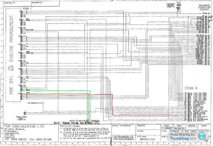
Just checking with those that know that the connections I have labelled in the picture below are the correct pins to bench test a MBE ECU?
I have Byker28i's excellent diagram here as well as the MBE files from SBD Motorsport here so am pretty confident that it's just +12V on pin 52 and GND on either 51 or 50 needed, but thought it super prudent just to check so that I don't stand any chance of blowing the sensitive TTL components inside!
Many thanks and an Arduino project coming the Cerbera's way soon

Oh, and I also checked against the ECU connector as per this image

I have Byker28i's excellent diagram here as well as the MBE files from SBD Motorsport here so am pretty confident that it's just +12V on pin 52 and GND on either 51 or 50 needed, but thought it super prudent just to check so that I don't stand any chance of blowing the sensitive TTL components inside!
Many thanks and an Arduino project coming the Cerbera's way soon
Oh, and I also checked against the ECU connector as per this image
Edited by Juddder on Thursday 9th March 17:07
thefrog said:
Sorry can't help but wondering what surprise you have in store for us.
(PS: Doubt Arduino is up to replacing the ECU, but I suspect some sort of monitoring / diagnostics is on the cards).
That one (PS: Doubt Arduino is up to replacing the ECU, but I suspect some sort of monitoring / diagnostics is on the cards).

This is from another (*totally un-related) project I am working on with a team using an Arduino as the diagnostic interface to the main computer...

The finished shield is much nicer and for the Cerbera we'll only need the RX/TX interface, so we can use a simple commercial shield, as we can do everything through the serial interface


Edited by Juddder on Thursday 9th March 19:46
Sounds interesting, I've been working on/off on an arduino based MBE->Bluetooth OBD but lacking time, it's dragging on. It's based on an Arduino with an OBD shield and an OBD->Bluetooth dongle.
The other issue with Arduino is debugging because you don't have access to the serial port while it's connected to the car. You're in essence coding and testing blind which is time consuming. I've recently put together an add-on shield with an extra serial port so I can get some debug data, it works but I have yet to try it all together in the car to debug.
Why OBD ? Because I use Harry's LapTimer on my iPhone and it does nice video overlays without having to use a separate application to merge videos and data, but needs OBD data for throttle opening and RPM amongst others (not all available from the ECU).
Edited by thefrog on Thursday 9th March 21:45
So I had the extra idea to check the Cerbera wiring diagrams and as per below 52 is connected to ECU power +12V and 50 & 51 and battery GND so appear to match the assumptions above
I think I'll meter the ECU terminals with the ECU cover off, just to double check, but at least that's multiple sources telling the same information (*almost unusual for TVR documentation )
)
I think I'll meter the ECU terminals with the ECU cover off, just to double check, but at least that's multiple sources telling the same information (*almost unusual for TVR documentation
)thefrog said:
Sounds interesting, I've been working on/off on an arduino based MBE->Bluetooth OBD but lacking time, it's dragging on. It's based on an Arduino with an OBD shield and an OBD->Bluetooth dongle.
We should talk! - I'll drop you a PM over the weekend 
BTW on the serial side of things you can use the other pins as Rx / Tx to enable multiple serial interfaces I believe so it might be possible if the Arduino is fast enough to switch between the two, or just use the internal pins as Rx / Tx and leave the debug interface open to use
https://www.arduino.cc/en/Tutorial/TwoPortReceive
Juddder said:
We should talk! - I'll drop you a PM over the weekend
BTW on the serial side of things you can use the other pins as Rx / Tx to enable multiple serial interfaces I believe so it might be possible if the Arduino is fast enough to switch between the two, or just use the internal pins as Rx / Tx and leave the debug interface open to use
https://www.arduino.cc/en/Tutorial/TwoPortReceive
This works Arduino-Arduino, but as far as I understand this doesn't work for an RS232 port to a computer for debug purposes. The shield I built is based on a MAX232 which does the signal adaptation from arduino I/O pins (8 and 10 iirc in my case).BTW on the serial side of things you can use the other pins as Rx / Tx to enable multiple serial interfaces I believe so it might be possible if the Arduino is fast enough to switch between the two, or just use the internal pins as Rx / Tx and leave the debug interface open to use
https://www.arduino.cc/en/Tutorial/TwoPortReceive
This is the schematic for the shield: https://arduinodiy.files.wordpress.com/2012/03/max...
I found some time today to test (in the car) and got some reliable data out of the ECU.
thefrog said:
This is the schematic for the shield: https://arduinodiy.files.wordpress.com/2012/03/max...
Looks cool - I bought one of these which will do the same thing freeing up the internal Rx/Tx ports - should be trying it all out over the weekend 
BTW did you use the serial lead as per the SBD Motorsports with the extra resistors on the ECU plug end?
I think I've finally understood why these are needed (and it's at least 17 years after the ECU was made so I think talking about it is fine)
According to this document from MBE, the ECU has two different modes of operation selected by grounding different pins on the ECU
The 941 EMS has one Serial port, the serial port has two fundamentally different
modes of operation

1. Byte Mode (For use with MBE’s Easimap Windows based tool)

2. Broadcast Mode (Normally used to transmit a set of 16 parameters to a
logging system)

Mode 1, Byte Mode, is enabled by holding the Fuel Trim and Ignition Trim inputs
at a voltage other than zero. This is easiest done by connecting a 914 mapping
box or connecting a proprietary MBE systems comms lead.

Mode 2, Broadcast Mode, is enabled by ensuring a nominally zero voltage on
the Fuel Trim and Ignition Trim inputs (or open circuit) AND enabling the data
logging feature using the Easimap application.
Internally the 9 Pin Connector inside the ECU has pins 6 and 7 connected to Fuel Trim and Ignition Trim respectively, and pin 1 connected to GND
Thus, as with the SBD Motorsport serial diagram if you connect pins 6 and 7 to pins 5 and 4 with a pull-down resistors to ground, and using +5V on pin 4 with resistor in-between as the switch, then it pulls the Fuel Trim and Ignition Trim high (+5V) which puts the ECU into Byte Mode for Mapping, and low (0V) by default for Broadcast mode

Ground is just rerouted from 5 to 1 as per the table below, but 5 and 1 are connected anyway, and Rx / Tx stay the same at 3 and 2 respectively
From our perspective we only need Broadcast Mode for receiving monitoring information, so these can be grounded, or as the documentation says left at open circuit so a normal lead should be fine with just ground re-routed

Edited by Juddder on Saturday 11th March 16:34
Broadcast mode is used by some data logging dashboards such as the AIM ones.
I've have a coiled lead that came with the car and that works will all the applications, including evoOlli's, aide's, etc...
Personally I'd stick with the query/response pattern rather than broadcast if you want to share your design with others, else you'll end up with confusion over which lead(s) to use.
Also, afaik the broadcast sequence can be changed with easimap, so if someone happens to have changed it, your sw won't be interpreting the correct values.
All imo
Greg
thefrog said:
The other issue with Arduino is debugging because you don't have access to the serial port while it's connected to the car.
Quoting myself LOL.To be clear, this is because the Arduino board I'm using has a built-in RS-232 port rather than USB meaning that once it's working, there is no need for the additional RS232 shield, this however is needed for testing if debug while running is required.
The components I am using are:
-Freeduino Serial v2.0
-Seeed CAN BUS Shield V1.2
-PLX Kiwi3 CanBus to Bluetooth OBD
-Homemade serial shield for debugging
thefrog said:
Quoting myself LOL.
First sign of going slightly mad I believe, Greg, or is that getting involved with ECUs and Arduinos thefrog said:
To be clear, this is because the Arduino board I'm using has a built-in RS-232 port rather than USB meaning that once it's working, there is no need for the additional RS232 shield, this however is needed for testing if debug while running is required.
The components I am using are:
-Freeduino Serial v2.0
-Seeed CAN BUS Shield V1.2
-PLX Kiwi3 CanBus to Bluetooth OBD
-Homemade serial shield for debugging
The components I am using are:
-Freeduino Serial v2.0
-Seeed CAN BUS Shield V1.2
-PLX Kiwi3 CanBus to Bluetooth OBD
-Homemade serial shield for debugging
- Funduino Mega 2560 (extra ports to drive the LCD shield)
- SainSmart LCD Keypad Shield (for display and input via the limited keypad)
- Linksprite Serial RS232 Shield v2 (for dual serial debugging as you can use the jumper to select alternative pins from D0 and D1 to be extra serial ports)
and here's a mock up (working sketch just not with real values) of what I think might work quite well for an Arduino ECU monitor
Especially as you can power it off the cigarette lighter socket as it will quite happily flatten +12V down to the +5V it needs and will boot up pretty instantly from starting the car (one of the things that I really want)

For my test bench I've verified that pin 52 is +12V input and 51, 50 and 49 (not documented) are GND and measured +5V across the 27256 EPROM between Vcc and GND so that all looks good

Arcade power supply running the +12V

Power test pin connections

+5V from the 27256

Also, it would be nice to use the LEFT an RIGHT buttons on the SainSmart LCD Shield to switch between different displays
Now I just need a few leads to arrive and start sending / reading the values back and forwards with the ECU... (I wish it will be that easy)
Gassing Station | Cerbera | Top of Page | What's New | My Stuff