Haynes manual wiring diagram- why is it not clear?
Discussion


I have a Haynes manual for my motorbike and am trying to make sense of the wiring diagram but it's really pissing me off why there are no legends apart from the wiring, no explanations of the tables etc:
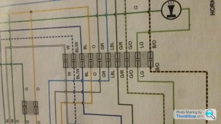
1) In the above The components in the greyed out boxes the circuit symbol with parallel lines- what exactly are please and what does it do. Those things are there at the start of every wire to every component so they must be important. surely not a capacitor- why an earth would there be a capacitor on every single wire right after every component It just makes no sense...
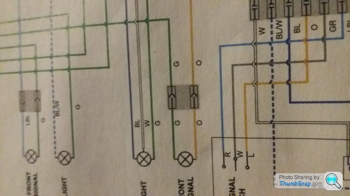
2) In the above :There's also the other kind of greyed out box: The one with the circuit symbol with the curvy arrow thing- that one doesn't look familar at all...
 |https://thumbsnap.com/Q0mTda2a[/url]
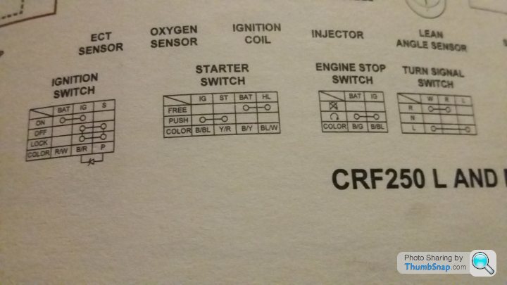
3) In the tables again no explanation: BAT, IG,S, W, N, The white unfilled circles with lines connecting them in the table boxes. R and L in turn signal box obviously means right and left... that's about all I can gauge in this annoying schematic. lock, free, push...

more

4) with the colour coded wires- are these the actual colours of the wires in real life?
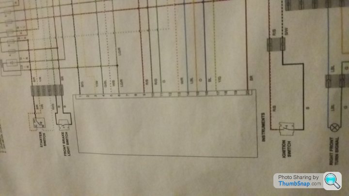
5) Finally, and possibly most confusing of all there's a huge box with numbered terminals 1-20 and wires coming out from each. Have no idea what this box is: could someone enlighten me please?
1) In the above The components in the greyed out boxes the circuit symbol with parallel lines- what exactly are please and what does it do. Those things are there at the start of every wire to every component so they must be important. surely not a capacitor- why an earth would there be a capacitor on every single wire right after every component
It just makes no sense...2) In the above :There's also the other kind of greyed out box: The one with the circuit symbol with the curvy arrow thing- that one doesn't look familar at all...
|https://thumbsnap.com/Q0mTda2a[/url]3) In the tables again no explanation: BAT, IG,S, W, N, The white unfilled circles with lines connecting them in the table boxes. R and L in turn signal box obviously means right and left... that's about all I can gauge in this annoying schematic. lock, free, push...
more
4) with the colour coded wires- are these the actual colours of the wires in real life?
5) Finally, and possibly most confusing of all there's a huge box with numbered terminals 1-20 and wires coming out from each. Have no idea what this box is: could someone enlighten me please?
1. Connectors joining two parts of the loom together
2. Not sure what you mean here
3. The white circles joined by a line simply indicate which wires would be connected when a switch is moved to a certain position. Possible switch positions in the vertical column, wire name/function in horizontal column. Bat - battery, ig - ignition etc etc. Look at each switch in the main diagram.
4. Should be. Although Haynes are never perfect in my experience. Get an official Honda manual to be 100% sure
5. Instruments (cluster) . It says that right next to it!
Edited by DuraAce on Monday 11th September 07:49
Edited by DuraAce on Monday 11th September 07:54
1)As said above, loom connectors - lots of wires joined in the same plug, which will be chunky and not something easy to play about with.
2) Also loom connectors, but this one will be just 2 wires and probably just spade/bullet connectors or similar.
3) The circles and lines show which poles of the switches are connected under which circumstances: name of pole at the top, circumstance on the left and wire colour at the bottom. So taking the simplest one there, the kill switch, when it's open the battery (black/green wire) is not connected to the ignition (black/blue wire); when it's closed the two are connected (and your bike will start).
4) The colours are ones that either Haynes found when they took their one apart or the colours released officially by the manufacturer. It's not unknown for colours to change during a production run (or someone to have played with things after), so it can only ever be a guide.
5) RTM
Ilovecbrs599999 said:
for 5) I read it said Instruments but what does that mean? and even if I did know- the numbers on their own 1-20 would surely be meaningless to me?
Sheeesh. Do you want a free course in electrics?! It means the instrument cluster connector behind the instrument panel (speedo etc.)
1-20 is the pin number assignment within that connector. Each pin hole in that 20 pin connector has its own identitying location number so you know what wire is in exactly what position.
Like I said, get hold of a Honda manual as they usually have more in depth info.
cool ok I understand thanks to you both. I'm still left a bit hanging when it comes to the instrument panel because it doesn't say what 1-20 are. there are no extra diagrams sadly and it doesn't say in either the owners manual nor haynes. in the instruments chapter i can only count 13 functions: speedo,tacho etc... which leaves me confused but ill call either honda or haynes tho
cheers
cheers
Edited by Ilovecbrs599999 on Monday 11th September 08:36
Ilovecbrs599999 said:
cool ok I understand thanks to you both. I'm still left a bit hanging when it comes to the instrument panel because it doesn't say what 1-20 are. there are no extra diagrams sadly and it doesn't say in either the owners manual nor haynes. in the instruments chapter i can only count 13 functions: speedo,tacho etc... which leaves me confused but ill call either honda or haynes tho
cheers
Did you even read my post above?!cheers
Edited by Ilovecbrs599999 on Monday 11th September 08:36
1-20 are the twenty uniqely identified pin holes in the connector for the instrument cluster. It is a 20 pin connector.
There are 20 holes for UPTO 20 different wires. In your case not all holes have wires in. This is because Honda will use this same connector in many other bikes, where they may all be used.
The connector will be marked so you can work which slot is pin 1 and so on. Better workshop manuals will provide diagrams to illustrate this.
DuraAce said:
Ilovecbrs599999 said:
cool ok I understand thanks to you both. I'm still left a bit hanging when it comes to the instrument panel because it doesn't say what 1-20 are. there are no extra diagrams sadly and it doesn't say in either the owners manual nor haynes. in the instruments chapter i can only count 13 functions: speedo,tacho etc... which leaves me confused but ill call either honda or haynes tho
cheers
Did you even read my post above?!cheers
Edited by Ilovecbrs599999 on Monday 11th September 08:36
Ilovecbrs599999 said:
oh...  so there's many more circuits not displayed on haynes wiring diagrams?
No. Like he says above, they only usually include the low tension side of the ignition system. IE the wiring diagram will stop at the ignition coil assembly. so there's many more circuits not displayed on haynes wiring diagrams?Pointless having a spark plug in a wiring diagram. It should be obvious that either the coil connects directly to the plug or is connected from plug to coil by the HT lead (depending on vehicle type)
The nice Honda dealer sent me a beautiful official Honda diagram 
They call it "combination meter" in the new diagrams and it has beautifully labelled pins

so to summarise electrics of a vehicle are 1) low tension is the primary winding of ignition coil and everything on that side
2) high tension is secondary which is energised by primary and is connected to spark plug which fires when field collapses...
Hardly Pandora's box there was only one other thing
They call it "combination meter" in the new diagrams and it has beautifully labelled pins
so to summarise electrics of a vehicle are 1) low tension is the primary winding of ignition coil and everything on that side
2) high tension is secondary which is energised by primary and is connected to spark plug which fires when field collapses...
Hardly Pandora's box there was only one other thing
Edited by Ilovecbrs599999 on Monday 11th September 20:51
Gassing Station | Home Mechanics | Top of Page | What's New | My Stuff