Extended/permanent connection to ECU diag port?
Discussion


So I have RS-AJP working. At the moment I've left the cover off the ECU with the data port hanging out of it, but don't want to leave it in this configuration for too long.
Has anyone, with the older style ECU (ie. without the 3pins on a fly lead), extended the port somehow?
I was thinking something along the lines of -
-Buy serial cable and cut one end off
-Solder some pins onto the ends (where from?)
-cut a hole into the ECU cover, find a grommet that fits and feed cable through
-Insert the pins directly into the ECU port
-Job done?
Although I have not actually done this with the ECU (mine has the 3 pin fly-lead), I would much rather not cut the front of the ECU to accommodate a plug.
Instead, I would buy a serial lead, cut the plug off one end, and solder the wires to the back of the ECU PCB - right onto the pads for the serial pins.
Use some fabric tape to secure the wire to the PCB and drill a small hole at the bottom of the ECU-case through which you can pass the wire and silicone seal it.
You can then secure the serial cable behind the passenger side panel, and pull it out when you need to.
Soldering directly to the PCB may sound frightening, but you can see many examples of this on YouTube - just search for “adding Bluetooth to car stereo” and you will find examples of people opening up their head-unit and soldering fly-leads to the PCB.
As-always, while working on the PCB you should wear an anti-static grounding wrist-band, or just take some copper wire, wrap it around your wrist and connect it with a crocodile clip to the ground on the ECU.
Good luck!
Edited by Imran999 on Tuesday 1st October 01:45
How much space is between the plug on the mainboard and the cover ?
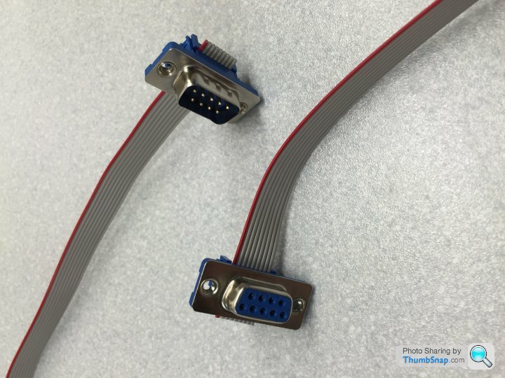
Instead of the plugs you have to solder you can use plugs which are meant for a ribbon cable. These are mostly very shallow. You can even remove the second bracket which is for the cable relief. Maybe these will fit ?
Search for "DB9 Ribbon Cable" and you will see what I mean.
Instead of the plugs you have to solder you can use plugs which are meant for a ribbon cable. These are mostly very shallow. You can even remove the second bracket which is for the cable relief. Maybe these will fit ?
Search for "DB9 Ribbon Cable" and you will see what I mean.
Nice idea, neater than me soldering pins onto bare cables.
Don't seem that readily available though.. I'll keep searching..
Something like this would be perfect if I can find it- https://uk.farnell.com/amp-te-connectivity/ne2509-...
If not, I can always get hold of the connectors and solder my own ribbon cable - https://uk.farnell.com/amp-te-connectivity/1-57478...
Think I prefer that to soldering directly to the board.
my previous owner cut a hole on the lid, plugged in the serial lead and it's run through under the dash to come out on the passenger side by the door. Easy with the excess tucked in so it can be pulled out. To protect the plug from damage it's got a plastic tube (possibly a hairdryer attachment) sealed over the slot.
Works well, I've left it like it for 13 years now...
Works well, I've left it like it for 13 years now...
I have an early ECU and didn't want to cut the box or leave it open.
I found a ribbon serial cable that fitted inside the box and the ribbon cable is flat enough that the box is now mostly closed. It the runs up the back of the dash board and appears in the hole under the stereo. It all tucks away when I'm not running the app or a laptop.
I found a ribbon serial cable that fitted inside the box and the ribbon cable is flat enough that the box is now mostly closed. It the runs up the back of the dash board and appears in the hole under the stereo. It all tucks away when I'm not running the app or a laptop.
Jimm218 said:
I have an early ECU and didn't want to cut the box or leave it open.
I found a ribbon serial cable that fitted inside the box and the ribbon cable is flat enough that the box is now mostly closed. It the runs up the back of the dash board and appears in the hole under the stereo. It all tucks away when I'm not running the app or a laptop.
I did the same but filed away a small notch in the side of the case to allow it to shut. Said notch is about 15mm wide and 1.5mm deep.I found a ribbon serial cable that fitted inside the box and the ribbon cable is flat enough that the box is now mostly closed. It the runs up the back of the dash board and appears in the hole under the stereo. It all tucks away when I'm not running the app or a laptop.
I did this with a 9-way bare socket, ground a couple of mm off the pins at the solder side, soldered on the wires flat and encapsulated in araldite. It fits under the cover easily.

Then it is possible for some phone types (Sony LT26i/Xperia S) to get a y-cable to power the phone and receive data down the same port. There is also a y-lead in the power side to power my dashcam.

Then you can fit the screen in a convenient location and have it come on every time the ignition is switched on.

Then it is possible for some phone types (Sony LT26i/Xperia S) to get a y-cable to power the phone and receive data down the same port. There is also a y-lead in the power side to power my dashcam.
Then you can fit the screen in a convenient location and have it come on every time the ignition is switched on.
Loving the ideas.
Charging isnt such a big deal, I have a wireless charger for my phone, so data via USB is fine... Although I would prefer a dedicated screen / tablet which I've seen a few people do. I've got a spare nexus 7 lying about, so might use that. It's just a bit slow to start up if it goes flat though..
Charging isnt such a big deal, I have a wireless charger for my phone, so data via USB is fine... Although I would prefer a dedicated screen / tablet which I've seen a few people do. I've got a spare nexus 7 lying about, so might use that. It's just a bit slow to start up if it goes flat though..
GT6k said:
I did this with a 9-way bare socket, ground a couple of mm off the pins at the solder side, soldered on the wires flat and encapsulated in araldite. It fits under the cover easily.
I did the same, with just a small cut in the flat ECU cover plate allowing the cable outThen when I went the see Joolz he pointed out that I could have used the three pin fly lead included in the loom - DOH!
Imran999 said:
Instead, I would buy a serial lead, cut the plug off one end, and solder the wires to the back of the ECU PCB - right onto the pads for the serial pins.
Use some fabric tape to secure the wire to the PCB and drill a small hole at the bottom of the ECU-case through which you can pass the wire and silicone seal it.
You can then secure the serial cable behind the passenger side panel, and pull it out when you need to.
This is what I did. Works great. Drilled a hole in the side of the case and sealed it.Use some fabric tape to secure the wire to the PCB and drill a small hole at the bottom of the ECU-case through which you can pass the wire and silicone seal it.
You can then secure the serial cable behind the passenger side panel, and pull it out when you need to.
aide said:
This should help..
From another (really really long) thread:
[thanks FYP!]
HTHFrom another (really really long) thread:
[thanks FYP!]
FarmyardPants said:
FarmyardPants said:
Links for making the above cable:
http://www.hobbytronics.co.uk/serial-db9-ribbon-fe...
http://www.hobbytronics.co.uk/serial-db9-ribbon-ma...
http://www.hobbytronics.co.uk/ribbon-cable-9 (Sold by the metre)
http://www.hobbytronics.co.uk/serial-db9-ribbon-fe...
http://www.hobbytronics.co.uk/serial-db9-ribbon-ma...
http://www.hobbytronics.co.uk/ribbon-cable-9 (Sold by the metre)
aide

Gassing Station | Cerbera | Top of Page | What's New | My Stuff