Yellow Ford Interior Lighting Relay
Discussion


Looking to get my interior light working.
The above Yellow relay is missing which some say the light can still be swiitched on but mine doesn't.
Checked all the usual things so just got a relay and thought I would test it before trying it in place.
Got a early edition 85GG 13C718 AA.
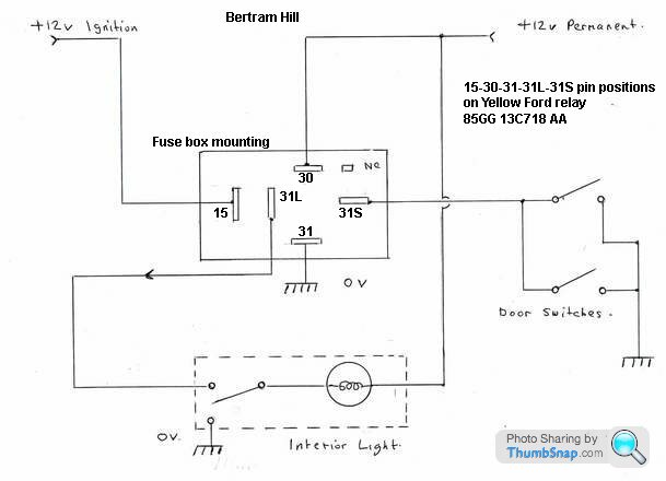
The interweb guides to testing a 5 pin relay I looked at didn't tie up with the pin numbers so I have borrowed Mr Hills drawing and added a few notes.
I have a battery and multimeter, so how should I test the relay?
Thanks

Drawing edited to show pins 30 and 31 the correct way round when the relay is in place
The above Yellow relay is missing which some say the light can still be swiitched on but mine doesn't.
Checked all the usual things so just got a relay and thought I would test it before trying it in place.
Got a early edition 85GG 13C718 AA.
The interweb guides to testing a 5 pin relay I looked at didn't tie up with the pin numbers so I have borrowed Mr Hills drawing and added a few notes.
I have a battery and multimeter, so how should I test the relay?
Thanks
Drawing edited to show pins 30 and 31 the correct way round when the relay is in place
Edited by lancepar on Tuesday 25th February 12:38
Be careful, steady as you go and all that
The diagram you've put numbers to is not of the relay terminals, it's of the relay holder
Hence you've as good as mirrored the diagram
Terminals 30 and 31 need reversing in your diagram, 30 is permanent + and 31 is earth/negative
Good job you posted here before connecting
That delay unit would have gone pop quicker than Iggy Pop can pop off a stage
Ok.
That's why I've marked on the drawing "fuse box mounting", It's not a view of the base of the relay itself but where the pins of the relay should locate when it is mounted in the fuse box..
I'll have another look tomorrow and check the pin numbers thought.
I really want to check the relay is working first anyway.
Penelope Stopit said:
Terminals 30 and 31 need reversing in your diagram, 30 is permanent + and 31 is earth/negative
You're right, my bad, glad someone is paying attention twas only a visual error though. And I've now corrected my first post.Here is a photo of the pins on the relay base.

Any idea how to test it or links to how to do it using the pin numbers on the Yellow relay or can I use the testing procedure for say a fuel pump relay with pins 30-85-86-87-87A?
Instructions here:
http://www.bertram-hill.com/courtesy-light.html
This will switch your courtesy and passenger footwell lights on when a door is opened. It will not fade them up or down unless the original yellow relay is in circuit.
The yellow relay? does in fact contain a bit of electronics and is prone to failure and discharging your battery when faulty I prefer to do away with the fading and have reliable lights. Replacing the courtesy/footwell bulbs with LEDS is a big improvement but make sure that they are +Ve earth type LEDS.
Edited by Loubaruch on Tuesday 25th February 22:50
Unless you are conversant with electronics and are able to draw the circuit it will be difficult to test.
Basically the relay as it is called will have a delayed fade circuit and from memory contains a few transistors, diodes capacitors and resistors.
I could not be bothered to go any further as a simple switch on and off is fine for me and has nothing to fail.
Basically the relay as it is called will have a delayed fade circuit and from memory contains a few transistors, diodes capacitors and resistors.
I could not be bothered to go any further as a simple switch on and off is fine for me and has nothing to fail.
Do you mean bench test it? If so
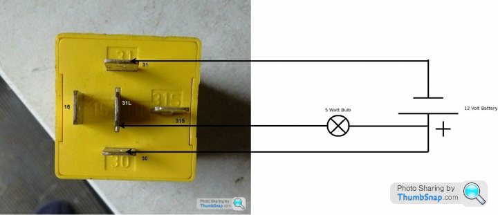
Once you've got as far as connecting it up as above diagram shows
Momentarily connect a negative from the battery to terminal 31 S of the relay (simulating the opening/closing of a door)
The 5 Watt bulb should remain illuminated for the pre-set time of the relay
Once the above has been proven to be ok
Momentarily connect a negative from the battery to terminal 31 S of the relay, the 5 Watt bulb has illuminated, now connect a positive from the battery to terminal 15 of the relay (simulating the ignition being switched on)
The 5 Watt bulb should be extinguished as soon as ignition on is simulated
It's best that you wire in a 3 or 5 amp in-line fuse to the battery positive for testing purposes (better be safe than sorry)
No Iggy Pop

Gassing Station | Griffith | Top of Page | What's New | My Stuff