
switched to earth v switched live
Discussion


I’m interested in using some modern US gauges in a British 1970s car and have been warned that they are switched to earth whereas we use switched live and that getting round this can be a little convoluted.
Can someone please offer a Luddites explanation of the difference and what the work would entail?
Can someone please offer a Luddites explanation of the difference and what the work would entail?
Thanks. That seems to make perfect sense. So in simple terms it’s the order the component and the switch are in? The US default is to have the switch after the component whereas older British cars tend to have the switch before.
If you are looking at say a fuel gauge is the device in the tank considered the switch and the gauge the component?
If you are looking at say a fuel gauge is the device in the tank considered the switch and the gauge the component?
this ties in with negative earth and positive earths.
used to have cars that the positive was earthed so it would make sense to have the negative switched. with a bulb not an issue but with a guage then it would be reversed and possibly cause some damage,
you need to do some more research on it to fully understand what is involved.
used to have cars that the positive was earthed so it would make sense to have the negative switched. with a bulb not an issue but with a guage then it would be reversed and possibly cause some damage,
you need to do some more research on it to fully understand what is involved.
With just a straight toggle switch it doesn't matter, but when you use transistors, mosfets and IGBT's to do the switching, it gets complicated.
Take a simple fuel injector. To make it work you put 12 volts positive on one side and ground the other side.
So to operate an injector the computer can either send 12 volts to the injector which will then go to the ground, or it can ground the injector which already has it's own 12 volt supply.
To send the 12 volts you would need a P-Channel mosfet.
To ground the 12 volts you would need an N-Channel mosfet.
P-Channel can handle less power, are less efficient and more expensive than N Channel.
The gauges in question are a speedo, tach, water temp and fuel. The car doesn’t currently have a tach.
From what I can work out the more complex one is the fuel gauge given the distance between the sender and the gauge but in general I would need to create a separate loom for the gauges and senders?
From what I can work out the more complex one is the fuel gauge given the distance between the sender and the gauge but in general I would need to create a separate loom for the gauges and senders?
This is what I am considering: https://www.speedhut.com/gauge/GRM4-DUAL-WF-01/1/D...
+
https://www.speedhut.com/gauge/GR4-DUALGPS-ST-01T/...
To replace the two clocks in this 1970s binnacle:
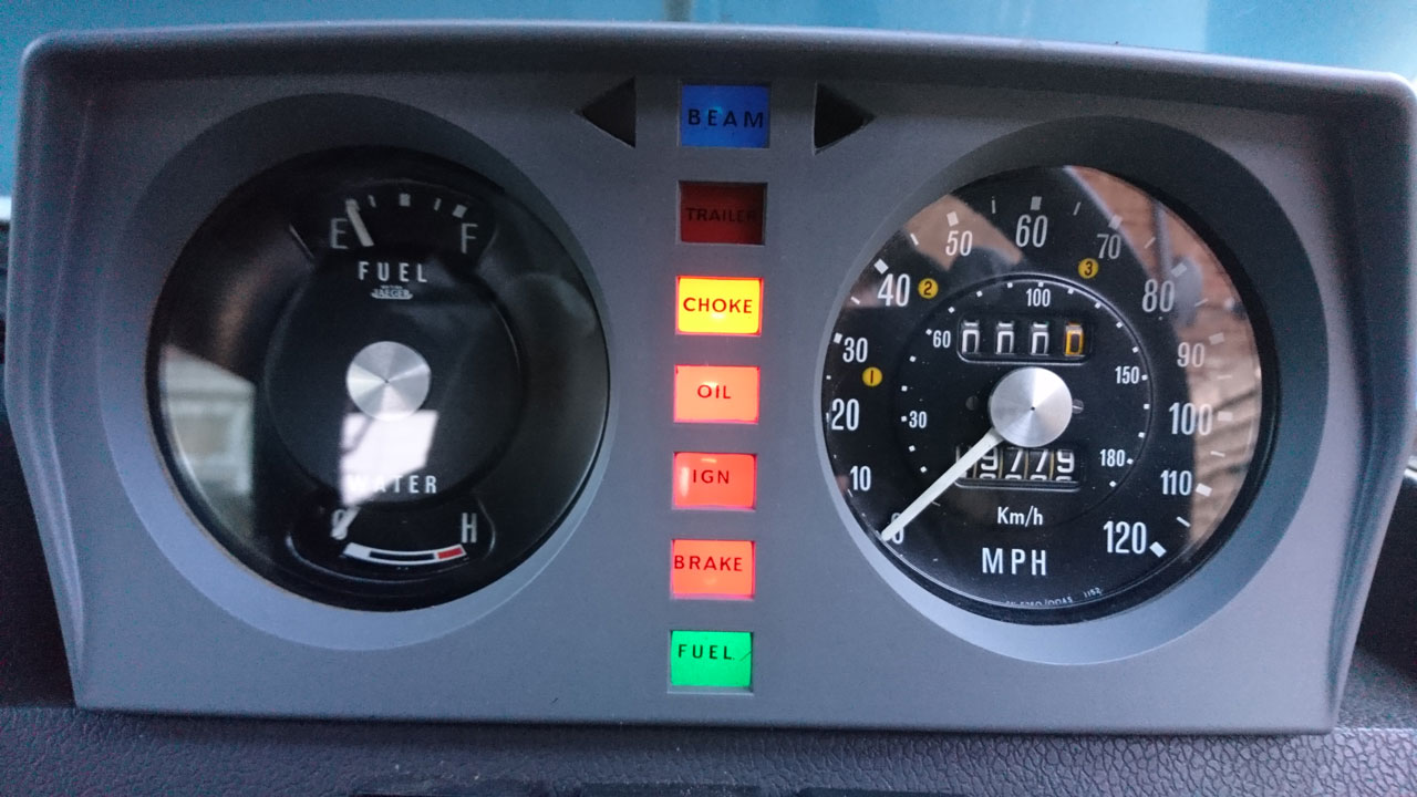
Now the car is fully on the road and being used more and more the shortcomings of the standard dash are coming to light and having just completed a long family trip it became time to consider whether to make some reversible changes.
The issues with the current set up are trivial for a classic but more pertinent when the car is in everyday use, which is the purpose of this car. These range from a speedo that under reads and the usual diving needle, lack of tacho which messes with my control freakery side, indicator lamps that cannot be seen due to steering wheel along with main beam and the fuel gauge also being blocked. The night lighting is also too poor to allow quick glances regardless of whether 5w bulbs are used instead of 2.2w etc.
The binnacle on my car is a Monteverdi binnacle and this gives a lot more flexibility for change but it is still a small working area and I like the fact that this US option allows me to retain the twin clock set up whereas the alternative would be a 4” speedo then a triangle of 3 2” clocks plus a more complex reworking of the warning lamps to get them into the space.
+
https://www.speedhut.com/gauge/GR4-DUALGPS-ST-01T/...
To replace the two clocks in this 1970s binnacle:
Now the car is fully on the road and being used more and more the shortcomings of the standard dash are coming to light and having just completed a long family trip it became time to consider whether to make some reversible changes.
The issues with the current set up are trivial for a classic but more pertinent when the car is in everyday use, which is the purpose of this car. These range from a speedo that under reads and the usual diving needle, lack of tacho which messes with my control freakery side, indicator lamps that cannot be seen due to steering wheel along with main beam and the fuel gauge also being blocked. The night lighting is also too poor to allow quick glances regardless of whether 5w bulbs are used instead of 2.2w etc.
The binnacle on my car is a Monteverdi binnacle and this gives a lot more flexibility for change but it is still a small working area and I like the fact that this US option allows me to retain the twin clock set up whereas the alternative would be a 4” speedo then a triangle of 3 2” clocks plus a more complex reworking of the warning lamps to get them into the space.
Ok, have now viewed the PDF https://www.speedhut.com/instructions/2in_and_258i...

Voltmeter - straightforward
Clock - straightforward
Gauges will work by using the ignition, ground and illumination cables that are already there at the dash plug
Extra cables need running to the senders, the senders are wired directly to the gauges and don't rely on the engine block earth
Your RR's original senders rely on engine block earths
IGNORE THIS BIT Fuel gauge is very likely to be of the same set-up rather than using the fuel tank earth
Now seen the following after reading post below
300 ohms fuel sender is what it's all about
Edited by Penelope Stopit on Sunday 26th July 11:39
Traditionally the temp and fuel gauges are fed from a positive supply (via voltage regulator) and the sensor for each is connected between the other side of the gauge and ground.
This means that the existing sensors are hard wired to ground (usually through the sensor body) and a single wire goes to the gauge.
It looks as though your proposed gauge is provided with a replacement temp sensor that has 2 terminals and no connection to its body. Install the temp sensor and the new 2 wire cable to the gauge and it will work fine.
I didn’t see anything about a fuel level sensor but they are almost exclusively connected to ground so I’d imagine the new gauge will work with the existing sensor.
ok now looking at this -
confirm your running a negative earth system - I think its more than likely, how ever the switched positive and switched negative terninology is what is confucing the issue here,
that was what led me to the pos/neg earth
if its an instrument cluster then these are quite strightforward, its all about matching what you have and what you want to put in and what is providing the sensors with the data. I see that one guage relies on satellite technology. for the speed.
This is all extremely useful. Thanks for taking the time to educate. It’s a 1972 Rangie so will be negative earth.
The speedo is, I think the easiest. The temp will need an additional wire. Is that likely to be the same for the tacho? Or will that still be a single wire from the distributor? The fuel gauge needs me to first check that the sender operates within their range but that may not require an additional wire as I can see that being the most awkward element?
The speedo is, I think the easiest. The temp will need an additional wire. Is that likely to be the same for the tacho? Or will that still be a single wire from the distributor? The fuel gauge needs me to first check that the sender operates within their range but that may not require an additional wire as I can see that being the most awkward element?
Tacho will need a single wire to the coil negative pulsed terminal
See PDF File https://www.speedhut.com/instructions/gps_dual_tac...

See PDF File https://www.speedhut.com/instructions/gps_dual_tac...
For the warning lights you could look at an LED upgrade? But if they're still dim after you fitted higher power bulbs then I'd check the 12V feed is OK. If the voltage is low then everything bar the speedo will be unhappy.
https://www.ebay.co.uk/itm/Land-Range-Rover-Classi...
Lubricating/replacing the speedo drive cable could improve the speedo behaviour quite a bit.
https://www.ebay.co.uk/itm/Land-Range-Rover-Classi...
Lubricating/replacing the speedo drive cable could improve the speedo behaviour quite a bit.
silentbrown said:
For the warning lights you could look at an LED upgrade? But if they're still dim after you fitted higher power bulbs then I'd check the 12V feed is OK. If the voltage is low then everything bar the speedo will be unhappy.
https://www.ebay.co.uk/itm/Land-Range-Rover-Classi...
Lubricating/replacing the speedo drive cable could improve the speedo behaviour quite a bit.
The warning lamps are bright enough. The bulbs are too far back from the dials to illuminate clearly. The lower set of warning lamps I have already upgraded to LEDs to solve their issue. https://www.ebay.co.uk/itm/Land-Range-Rover-Classi...
Lubricating/replacing the speedo drive cable could improve the speedo behaviour quite a bit.
Speedo cable is new and works as brilliantly as they ever did.
 . It just dives +/- 10mph which is a pain in 30s or average speed motorways etc.
I already use a GPS speedo via the phone. There is a general argument as to whether GPS speedos are legal but the car is exempt from MOTs and it would be declared with my insurance to stop them being arses.
Ultimately, the whole speedo issue is driven by the fact that traffic police are now all digital so it seems statistically unlikely that if there are no real police to police the really basic stuff then there won’t be many dedicated to taking a car apart to check what type of speedo it is using.
Just harking back to the original question, it is quite common (in my experience) for the horn to be earth switched, which is why I chose it for my example.
As for bouncy speedos (if it bothers you enough), you could consider getting something like a Terratrip speedo probe. Cut the speedo cable; peel back a short length of sheath each side, insert probe and stick it all back together again (that's from memory, might be wrong in detail). You then have an electrical pulse which you can feed into a modern speedo - obvs needs calibrating.
As for bouncy speedos (if it bothers you enough), you could consider getting something like a Terratrip speedo probe. Cut the speedo cable; peel back a short length of sheath each side, insert probe and stick it all back together again (that's from memory, might be wrong in detail). You then have an electrical pulse which you can feed into a modern speedo - obvs needs calibrating.
Gassing Station | Home Mechanics | Top of Page | What's New | My Stuff