
Mechanical Engineering Help - Robot Lawnmower
Discussion


I'm working on some personal projects of various things. I have a software engineering background so the code and electronics stuff is fine, but the CAD design and mechanical engineering stuff I am learning on the go. These just are personal s ts and giggles projects, not for anything commercial or course related.
I have a specific problem right now. Im creating a robotic lawnmower, I want to have electronic blade height adjustment. This is what I have so far. I have been through about 8 versions and each time as I get to the end I realise it wont work.


The top plate will be fixed to the chassis. The main DC motor (cylinder in centre) will be attached to the bottom plate. Prior to this design it seemed fine as I had it the other way round, So the flange nuts were bolted to the motor plate. But the problem I had there is the lead screws would descend past the blade which was no good. I have gone for 1 stepper motor and a timing belt (not in diagram). Reason for that is weight, cost and also I dont trust 4 motors to perform in perfect unison and not go out of step.
The problem I have now is fairly obvious. The GT2 pulleys are not attached to the motor plate and are just going to machine themselves into the metal plate. I've run out of talent and could do with some advice from someone who knows that they are doing please?
ETA - also bigger problem is the drive shaft cant collapse as the motor plate moves
ts and giggles projects, not for anything commercial or course related.I have a specific problem right now. Im creating a robotic lawnmower, I want to have electronic blade height adjustment. This is what I have so far. I have been through about 8 versions and each time as I get to the end I realise it wont work.
The top plate will be fixed to the chassis. The main DC motor (cylinder in centre) will be attached to the bottom plate. Prior to this design it seemed fine as I had it the other way round, So the flange nuts were bolted to the motor plate. But the problem I had there is the lead screws would descend past the blade which was no good. I have gone for 1 stepper motor and a timing belt (not in diagram). Reason for that is weight, cost and also I dont trust 4 motors to perform in perfect unison and not go out of step.
The problem I have now is fairly obvious. The GT2 pulleys are not attached to the motor plate and are just going to machine themselves into the metal plate. I've run out of talent and could do with some advice from someone who knows that they are doing please?
ETA - also bigger problem is the drive shaft cant collapse as the motor plate moves
Edited by Scabutz on Sunday 4th July 20:09
That looks quite neat, however if I understand it correctly -
The stepper motor assembly will have to be attached to the bottom plate, so that its pulley stays in line with the others.
You will need thrust bearings in the bottom plate below the pulleys, and these will have to take thrust both up and down. You will also need collars or similar, attached to the leadscrews below the bottom plate to transfer the upward movement.
To me, it seems a lot of components for what it has to do. I think for simplicity and cost-effectiveness you should aim for a single leadscrew perhaps directly driven by the stepper motor, and some form of sliding guide rails (ideally only one) to keep everything in line.
That is assuming the bottom plate has to move vertically. If a small angular movement is permissible, then it could be pivoted at one end which opens other possibilities for the height adjustment.
Scabutz said:
I considered that. But that will need individual stepper motors at each corner. Unless the rear wheels were on a sub-assembly and I just adjusted that? But then would the motor needs to be on a pendulum housing to keep it level as the rear went up and down.
Keep it simple and reliable, single large stepper serving all wheels through linked levers. Fixed shafts per axle, cam adjusters that are linked.Hawkshaw said:
To me, it seems a lot of components for what it has to do. I think for simplicity and cost-effectiveness you should aim for a single leadscrew perhaps directly driven by the stepper motor, and some form of sliding guide rails (ideally only one) to keep everything in line.
That is assuming the bottom plate has to move vertically. If a small angular movement is permissible, then it could be pivoted at one end which opens other possibilities for the height adjustment.
Thats what I was wondering. I watched a teardown of a commercial robot mower and it had a single plastic lead screw driven in parallel by a motor with gears and a spring loaded thread section. The main motor slid up and down on rails. Looked a very slick mechanism but wonder how I can replicate at home with basic tools (I have a 3d printer and basic CNC machine).That is assuming the bottom plate has to move vertically. If a small angular movement is permissible, then it could be pivoted at one end which opens other possibilities for the height adjustment.
Pivoting would work well, but I think the blade would need to pivot independently to remain level. I have read about pendulum housings, but cant find any info on how to produce one
Loads of options... I do quite like the adjusting the cutting deck option rather than the whole mower height.
You could use a planetary gear with a stepper motor and the leads crews in the scheme you have.
You could use a levelling wedge type arrangement.
You could have to motor mounted on a parallel arm / wishbone arrangement, adjusted with the stepper motor and lead screw.
You could use a planetary gear with a stepper motor and the leads crews in the scheme you have.
You could use a levelling wedge type arrangement.
You could have to motor mounted on a parallel arm / wishbone arrangement, adjusted with the stepper motor and lead screw.
Scabutz said:
Pivoting would work well, but I think the blade would need to pivot independently to remain level. I have read about pendulum housings, but cant find any info on how to produce one
How level does it have to be though? Clearly the cut will only be optimum when the blade is level, but the lawn won't be anywhere near level whatever you might like to think.Some form of parallel motion would keep it all level.
Hawkshaw said:
Scabutz said:
Pivoting would work well, but I think the blade would need to pivot independently to remain level. I have read about pendulum housings, but cant find any info on how to produce one
How level does it have to be though? Clearly the cut will only be optimum when the blade is level, but the lawn won't be anywhere near level whatever you might like to think.Some form of parallel motion would keep it all level.
My latest attempt. Single lead screw with a flange nut mounted to the motor plate. Shaft with a flange bearing at the other end. I have extended the plates so when the motor plate rises it wont smash the disk into the lead screw.

How it will be mounted. Rough chassis for now.

Specd it for now with an 8mm lead screw and shaft. Wondering if 10 or 12mm would be better for extra stability,
Reasonably happy with that result, thanks for the advice. Think I will mock it up with some plastic plates first before I order the metal plates to be made. Have limited meta working capability so getting the plates made for me and using 20x20 extrusion for the main chassis.
Chassis and body work next. Might go for a batmobile sleek look and maybe add some Knightrider leds on the front for sts and giggles
How it will be mounted. Rough chassis for now.
Specd it for now with an 8mm lead screw and shaft. Wondering if 10 or 12mm would be better for extra stability,
Reasonably happy with that result, thanks for the advice. Think I will mock it up with some plastic plates first before I order the metal plates to be made. Have limited meta working capability so getting the plates made for me and using 20x20 extrusion for the main chassis.
Chassis and body work next. Might go for a batmobile sleek look and maybe add some Knightrider leds on the front for s
ts and gigglesInitialDave said:
I'd use a lead screw operating a parallelogram linkage, think something like a scissor lift or basic car jack.
Ok, something like this?https://www.amazon.co.uk/Stainless-Steel-Stand-Tab...
Stepper motor driving the screw and the main DC motor mounted in the middle of the table. I like that. Certainly looks more stable and compact as well.
Back to the drawing board. Version 320994 coming up
Thanks!
ETA - the screw goes right through the middle though so no room for the motor?
Looking at your first picture, that's the sort of thing, but have you plotted the changes in geometry during rise and fall?
The lower plate has to hinge at its left hand end, so the mounting here must be a pivot or ball joint. The plate will move on a radius, so at the right hand end there must be a pivot at the leadscrew attachment, and the stepper motor must also pivot to allow the leadscrew to follow the radius.
Best to arrange a 3 point mounting for stability, so maybe two pivots on the left, one at each corner?
You can learn a lot by mocking these things up with wood and card.
Hawkshaw said:
Looking at your first picture, that's the sort of thing, but have you plotted the changes in geometry during rise and fall?
The lower plate has to hinge at its left hand end, so the mounting here must be a pivot or ball joint. The plate will move on a radius, so at the right hand end there must be a pivot at the leadscrew attachment, and the stepper motor must also pivot to allow the leadscrew to follow the radius.
Best to arrange a 3 point mounting for stability, so maybe two pivots on the left, one at each corner?
You can learn a lot by mocking these things up with wood and card.
The lower plate has to hinge at its left hand end, so the mounting here must be a pivot or ball joint. The plate will move on a radius, so at the right hand end there must be a pivot at the leadscrew attachment, and the stepper motor must also pivot to allow the leadscrew to follow the radius.
Best to arrange a 3 point mounting for stability, so maybe two pivots on the left, one at each corner?
You can learn a lot by mocking these things up with wood and card.
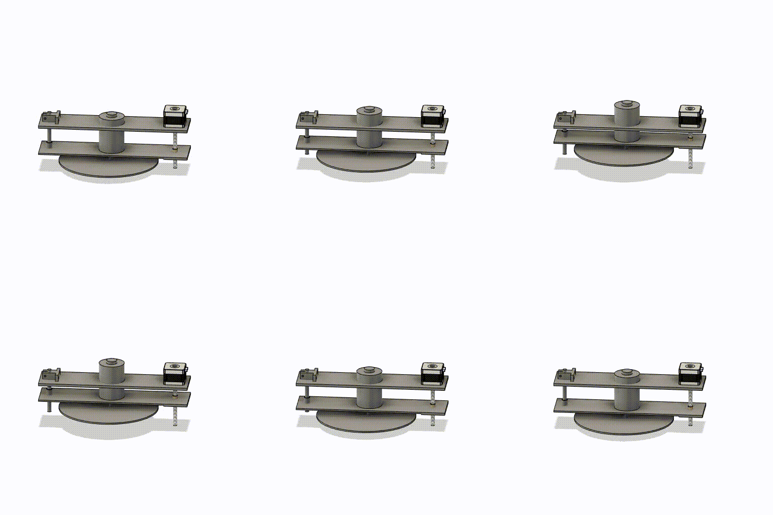
This is how Ive modelled the motion. Not sure I get you on the hinge part? The part on the left is a flanged bearing ( https://www.automotioncomponents.co.uk/en/catalog/...). On the right is a flanged t nut
Yes 3 point mount would be more stable I think.
Problem I still have is the lead screws poke out still
This guy seems to have cracked it.
http://www.liming.org/router/lift.html
Should give me what I need without the lead screw dangling down
http://www.liming.org/router/lift.html
Should give me what I need without the lead screw dangling down
Sometimes you have to think outside the box; this doesn't need anything other than manual height adjustment.
If you want it to auto-adjust, just because, so you can let it loose on longer grass and have it cut it down in steps, then the simplest option might be to adjust the position of the blades relative to the rest of the machine. Let the motor drive a shaft with a sliding and keyed second shaft in the end, add your height adjustment to the second shaft perhaps.
Also, build it in Lego first, it'll be easier to get the a mechanical solution that works that way.
Thebaggers said:
Make the wheels adjustable instead, leave this all fixed, take Inspiration from single point height adjustment on std mowers.
This is basically what the current generation Worx robot mowers do.. they have a floating deck that cuts the grass, so it can adjust itself as necessary to stop itself grounding out.If you mount the motor within a housing which has a coarse male screw thread around it, and fit this in a housing in the deck with a matching female thread, a single servo could rotate the motor through the necessary angle to cover the full height adjustment. A spring applying a constant force in one vertical direction would allow the 'thread' to be in the form of an annular ramp with a single-sided contact face, so you don't have a normal thread that would clog up with doesn't dirt and grass.
Another approach would be to have a spline on the motor/blade shaft and move it up and down through the motor, leaving the motor fixed.
Another approach would be to have a spline on the motor/blade shaft and move it up and down through the motor, leaving the motor fixed.
Gassing Station | Computers, Gadgets & Stuff | Top of Page | What's New | My Stuff