Bath Taps Installation Help Please
Discussion


Hello all.
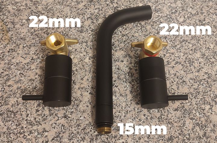
Some help with my new bath taps please. These (along with everything else for my new ensuite) came from a local bathroom supplier/plumbers merchants. (I can ask them for assistance on Monday, they're a good and reputable company) but still would like a PH opinion.
Three questions: Firstly, as you can see, the valves have 22mm fixings, and that's fine, as I have 22mm on both hot and cold coming in to the ensuite. However, the spout is only 15mm. Should I have a spout with a 22mm connection? Surely the 15mm negates and advantage of 22mm, or it the case that 22mm for as far as possible and then down to 15mm is fine?
Secondly, what items/connections do I need to go into and out of the valves and on to the spout please? I get that I'll be going into a T-Piece (presumably with 2x22m fittings and a 15mm 'output' which then connects to the spout, but I'm unsure about what goes into the threads on either side of the valves.
Finally, there appears to be no fixing as such for the spout. My assumption is that the T-piece will be what supports it, and given that T-piece will be between the two valves which will be solidly fixed to a batten I guess that's OK. (I have those interlocking wall panels to fit through, but they won't provide any real support, just a bit of protection from the spout being knocked).
Thanks for any help.
Are there no shrouds to go over the feeds and the spout ? Otherwise youre going to have to be incredibly precise cutting tiles or whatever will be covering the wall
You need 2 of 3/4 inch male iron to 22mm compression for the hot and cold inlets , then if there is nothing else in the box youll have to connect the hot and cold outets to the spout using 3/4 male iron to 15 or 22mm connectors a 15 or 22mm tee and a 1/2 or 3/4 inch female iron to the required size of copper . I would use a wall plate elbow to give the spout rigidity.
This is fairly advanced diy with a lot to consider , positions , depths , they normally come as a kit to make installation more straightforward
Hello all.
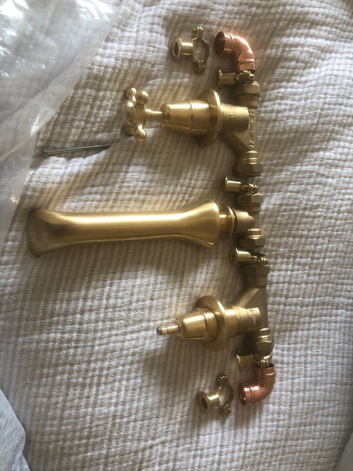
As there have been a couple of comments as quick response from me, and admisison that yes, all the threads are 3/4". My mistake, sorry.
There are shrouds to go over everything, so the install will look neat, and there are also some plastic 'cones' which temporarily fit over the valves to allow you to set them at the correct depth from the wall.
Thanks to miroku1 for specifying the parts, and I will pop back to the plumbers merchants tomorrow and buy what's needed. This I think answers Mr Pointy's question.
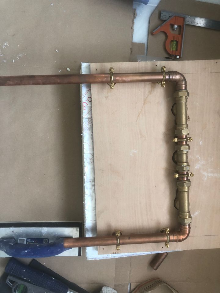
It is a bit complicated I agree, but in my favour is the fact that this is all being fitted into an interlocking wall board that I am yet to fit. So I can cut the board to size, then fit the plumbing, and leave me a simple 2x22mm push fit onto the incoming copper (or I might go compression and copper), the pipes are very accessible.
Bath then goes in to position, with the only connection on that being straight through to the outside wall.
Cheers all.
As there have been a couple of comments as quick response from me, and admisison that yes, all the threads are 3/4". My mistake, sorry.
There are shrouds to go over everything, so the install will look neat, and there are also some plastic 'cones' which temporarily fit over the valves to allow you to set them at the correct depth from the wall.
Thanks to miroku1 for specifying the parts, and I will pop back to the plumbers merchants tomorrow and buy what's needed. This I think answers Mr Pointy's question.
It is a bit complicated I agree, but in my favour is the fact that this is all being fitted into an interlocking wall board that I am yet to fit. So I can cut the board to size, then fit the plumbing, and leave me a simple 2x22mm push fit onto the incoming copper (or I might go compression and copper), the pipes are very accessible.
Bath then goes in to position, with the only connection on that being straight through to the outside wall.
Cheers all.
I’ve skim read, and apologies if I’ve got this wrong but looks like you are facing the same situation I was last year…
Taps and spout and no obvious way to make the thru wall fitting work if you couldn’t access the rear.
My solution…
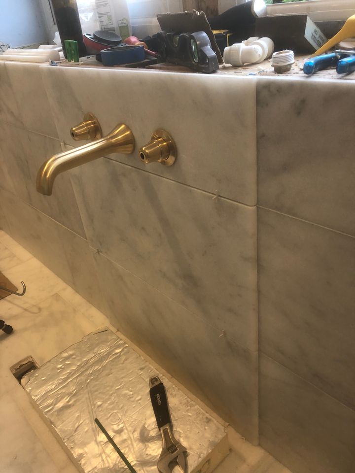
Final result…
I’ll try find a link for the missing bit I had to source in the middle + thread extender to make it work!
Found it…
https://www.plumbingsuppliesdelivered.co.uk/produc...
Got the 3/4 extensions from Amazon

Taps and spout and no obvious way to make the thru wall fitting work if you couldn’t access the rear.
My solution…
Final result…
I’ll try find a link for the missing bit I had to source in the middle + thread extender to make it work!
Found it…
https://www.plumbingsuppliesdelivered.co.uk/produc...
Got the 3/4 extensions from Amazon
Edited by Danns on Sunday 10th November 13:03
Edited by Danns on Sunday 10th November 13:16
Sorry to bump my own thread, but I'm fitting my taps now. We're almost certainly getting an unvented cyclinder installed, so the pressure problem goes away.
What I'm not sure about is how to connect in and out of those valves. It seems there's no provision for any kind of O-ring, or for a compression olive. Is this just a case of PTFE tape?
Whatever the correct answer, could someone point me in the direction of a suitable T-connector into which the spout will screw, and also suitable connectors for the valve input sides to get me to 15mm incoming speedfit with the fewest connections required please.
Please note that as correct above, the threads are all 3/4".
Thank you :-)
You’re going to have fun installing this !
You need a 3/4 inch female branch tee to 22mm compression. Assuming the taps are 3/4 inch female in and out , you’ll need 2 of 3/4 x 22mm compression straight connectors , plus 2 of 3/4 inch to 1/2 inch brass bushes then 2 of 1/2 inch male iron to 15mm speedfit either bent or straight depending upon pipe layout .
I still use ptfe tape , about 22 wraps on each thread , I have used liquid ptfe successfully just don’t trust it , had something assembled at factory recently using liquid ptfe and it leaked .
Good luck
miroku1 said:
You’re going to have fun installing this !
You need a 3/4 inch female branch tee to 22mm compression. Assuming the taps are 3/4 inch female in and out , you’ll need 2 of 3/4 x 22mm compression straight connectors , plus 2 of 3/4 inch to 1/2 inch brass bushes then 2 of 1/2 inch male iron to 15mm speedfit either bent or straight depending upon pipe layout .
I still use ptfe tape , about 22 wraps on each thread , I have used liquid ptfe successfully just don’t trust it , had something assembled at factory recently using liquid ptfe and it leaked .
Good luck
Thanks. Yes my research did suggest that I'd be introducing a lot of points of failure behind a panel that I would hope never to have to remove. Having said that, I will be installing the panels such that I could get them out in the event of a leak.You need a 3/4 inch female branch tee to 22mm compression. Assuming the taps are 3/4 inch female in and out , you’ll need 2 of 3/4 x 22mm compression straight connectors , plus 2 of 3/4 inch to 1/2 inch brass bushes then 2 of 1/2 inch male iron to 15mm speedfit either bent or straight depending upon pipe layout .
I still use ptfe tape , about 22 wraps on each thread , I have used liquid ptfe successfully just don’t trust it , had something assembled at factory recently using liquid ptfe and it leaked .
Good luck
Taps are indeed 3/4" in and out, and if I understand correctly, these are the type of thing I need to connect into the taps:
https://www.screwfix.com/p/flomasta-brass-compress...
Sorry to be a pain, and this is where the PTFE question cropped up, but what does the actual sealing when that is screwed in to the tap? Just PTFE, or maybe a fibre washer goes on. I just can't visualise where there's any actual sealing taking place.
Thank you!
Edit to add corrected photo :-)
Edited by Turtle Shed on Thursday 21st November 23:19
Yes you’re correct regarding the fittings required to connect the hot and cold to the outlet tee , don’t forget cold on the right .
Basically wrap the ptfe counterclockwise so that it tightens on with the direction of rotation, the ptfe seals the male and female threads it will also seal between the shoulder of the male fitting as it tightens against the female
Basically wrap the ptfe counterclockwise so that it tightens on with the direction of rotation, the ptfe seals the male and female threads it will also seal between the shoulder of the male fitting as it tightens against the female
Gassing Station | Homes, Gardens and DIY | Top of Page | What's New | My Stuff