Tamiya 58414 CR01 Unimog build
Discussion


Afternoon all - thought this might be of interest to others. Found the kit fairly sensibly priced from Germany on eBay. I'm building stock with two steering servos as I'd heard the turning circle isn't great otherwise. Body will be metallic green.
This'll likely take a good few weeks now I'm back at work. I plan on one photo per stage of the build but we'll see how that goes.
First stage is to build the suspension links. Careful attention needed as it's not immediately clear which way round some of the parts go, but there is a side-on view. The instructions are a bit more cluttered than normal for Tamiya.
Next those links and the side plates are assembled to the chassis rails. Need to carefully count the holes to get them in the tight positions, and the angle of the drawing doesn't make it clear which way up the rails go - they look straight in the instructions.
Quite a few threadlocked nut/bolt connections through plastic, so instead of the supplied red stuff (which attacks plastic) I'm using PVA. Also some care needed as there are six different lengths of bolts in bag A.
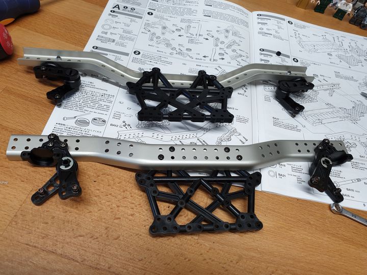
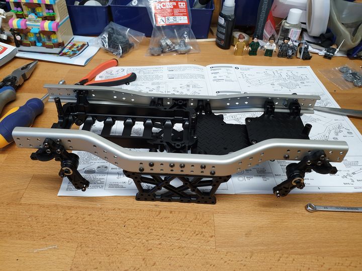
The centre bit gets assembled from three parts, then sandwiched between the rails. Don't forget to put the anti-roll bars between the suspension links, because once you've gone up the six (I think) bolts on each side it's impossible to get them in without taking it apart a bit. You can imagine how I know.
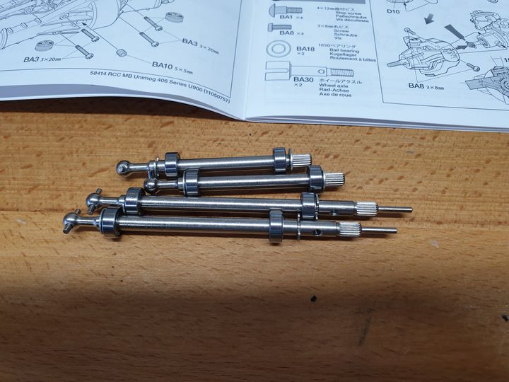
Last stage of the first two pages - driveshafts. Fairly straightforward.
All good thus far!
This'll likely take a good few weeks now I'm back at work. I plan on one photo per stage of the build but we'll see how that goes.
First stage is to build the suspension links. Careful attention needed as it's not immediately clear which way round some of the parts go, but there is a side-on view. The instructions are a bit more cluttered than normal for Tamiya.
Next those links and the side plates are assembled to the chassis rails. Need to carefully count the holes to get them in the tight positions, and the angle of the drawing doesn't make it clear which way up the rails go - they look straight in the instructions.
Quite a few threadlocked nut/bolt connections through plastic, so instead of the supplied red stuff (which attacks plastic) I'm using PVA. Also some care needed as there are six different lengths of bolts in bag A.
The centre bit gets assembled from three parts, then sandwiched between the rails. Don't forget to put the anti-roll bars between the suspension links, because once you've gone up the six (I think) bolts on each side it's impossible to get them in without taking it apart a bit. You can imagine how I know.
Last stage of the first two pages - driveshafts. Fairly straightforward.
All good thus far!
More progress today. First I went back and swapped ten screws from previous stages - the instructions show each screw slightly longer than it actually is, so I'd used up some I still needed. Ooops.
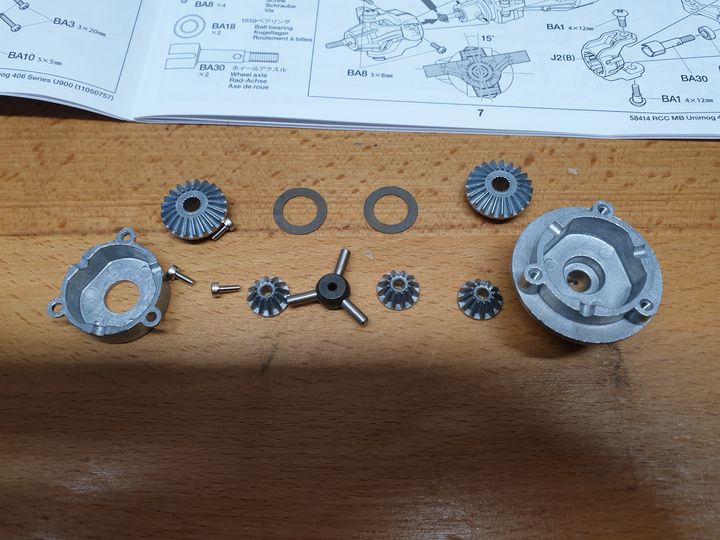
First job is building the differentials. All metal casings and gears. These bits (and quite a lot of ceramic grease - worth, I'd say, buying the bigger tube with the nozzle on the end):
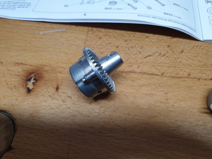
...turn into one of these (then you make another the same):
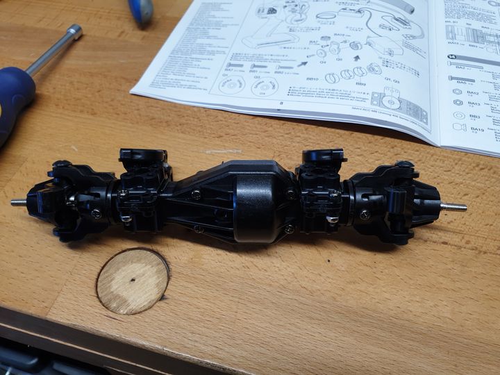
Then it's the axles. First the drive gear goes on, mounted on two bearings. Don't forget the shim between the outside bearing and the E-clip that holds the shaft in place.
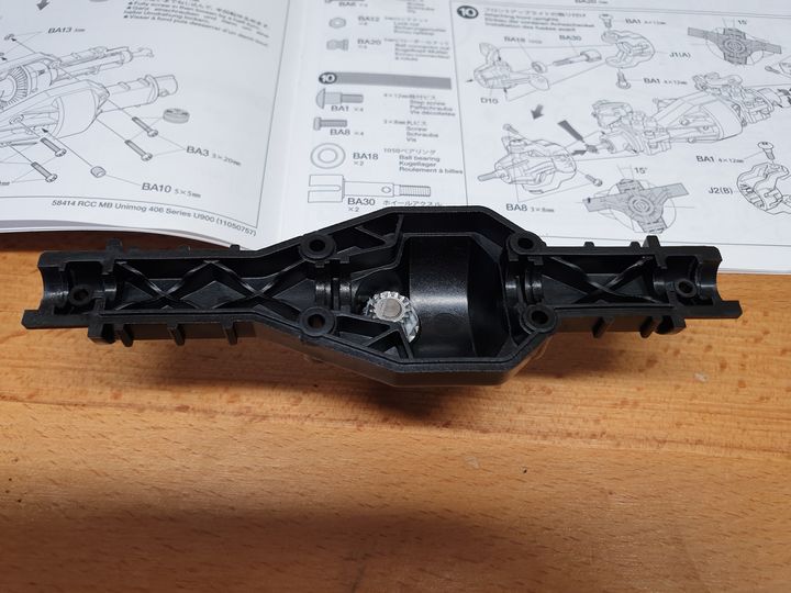
The driveshafts go into the differential ends, and the assembly is placed into the casing. At this point a little pin screws into the left hand end to lock the diff - it can be removed later by unscrewing a grub screw from the axle housing and then unscrewing the pin, to unlock the diff. I'm building them locked as I'll have four wheel steering so should still get a decent turning circle.

Other half of the housing goes on, and is clamped together by the suspension mounts which screw around each end. Red threadlock applied to the ball ends after the screw went through the plastic.
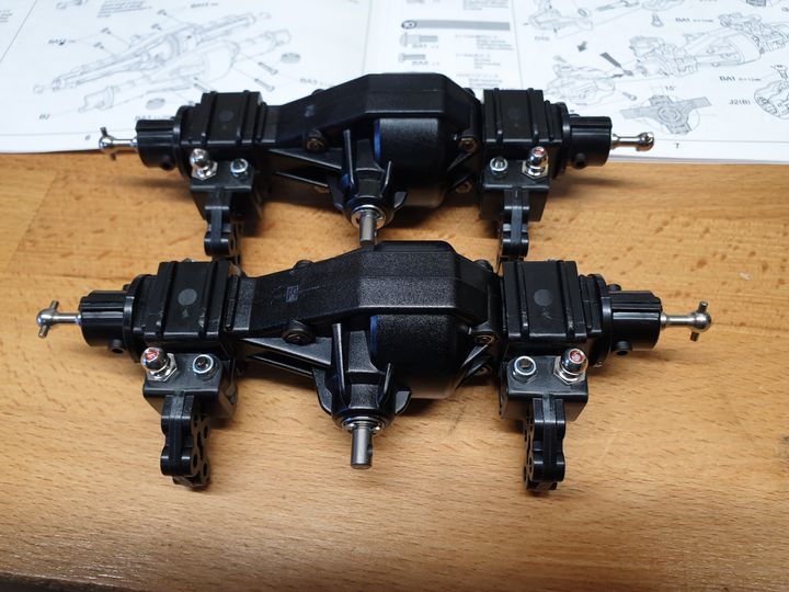
Spring catchers and damper connections added.
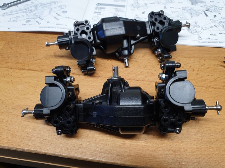
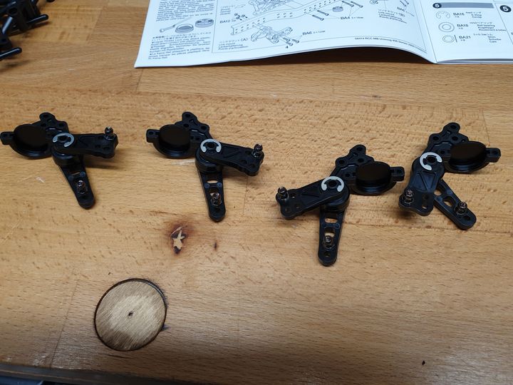
Steering knuckles get assembled (bits on the right, result on the left) - both axles have the same thing. The back axle normally gets its knuckles locked with a bar that goes across.
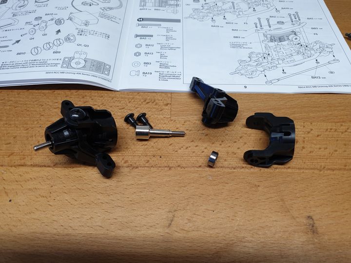
And then they're fixed onto the axles. The caster angle is different front and rear, facilitated by there being different slots to locate the knuckles onto the axle.
Thus endeth Bag A of the RC parts. I'm now slightly stuck as I'd not spotted that the kit doesn't come with two servo savers, so have placed a £10 order via eBay for Tamita part 51000 which is the Q sprue, the three circular springs, and some fixings. That should arrive next week, so I'll probably make a start on the body in the meantime.
I've also got the steering mixes set up on my shiny new FlySky NB4+, and tested that the servos work. Jolly clever being able to assign switches to go between "normal" AWS, front only, crab steer, and rear only. I think it's possible to also adjust the rear steer angle on the fly but I've not quite puzzled that one out yet.
First job is building the differentials. All metal casings and gears. These bits (and quite a lot of ceramic grease - worth, I'd say, buying the bigger tube with the nozzle on the end):
...turn into one of these (then you make another the same):
Then it's the axles. First the drive gear goes on, mounted on two bearings. Don't forget the shim between the outside bearing and the E-clip that holds the shaft in place.
The driveshafts go into the differential ends, and the assembly is placed into the casing. At this point a little pin screws into the left hand end to lock the diff - it can be removed later by unscrewing a grub screw from the axle housing and then unscrewing the pin, to unlock the diff. I'm building them locked as I'll have four wheel steering so should still get a decent turning circle.
Other half of the housing goes on, and is clamped together by the suspension mounts which screw around each end. Red threadlock applied to the ball ends after the screw went through the plastic.
Spring catchers and damper connections added.
Steering knuckles get assembled (bits on the right, result on the left) - both axles have the same thing. The back axle normally gets its knuckles locked with a bar that goes across.
And then they're fixed onto the axles. The caster angle is different front and rear, facilitated by there being different slots to locate the knuckles onto the axle.
Thus endeth Bag A of the RC parts. I'm now slightly stuck as I'd not spotted that the kit doesn't come with two servo savers, so have placed a £10 order via eBay for Tamita part 51000 which is the Q sprue, the three circular springs, and some fixings. That should arrive next week, so I'll probably make a start on the body in the meantime.
I've also got the steering mixes set up on my shiny new FlySky NB4+, and tested that the servos work. Jolly clever being able to assign switches to go between "normal" AWS, front only, crab steer, and rear only. I think it's possible to also adjust the rear steer angle on the fly but I've not quite puzzled that one out yet.
Edited by Sporky on Sunday 12th January 10:26

TGCOTF-dewey said:
One tip is, junk the awful dog bone joints, and upgrade to proper universal joints. Dog bones are awful fragile things.
If I was going to use it a lot I probably would, but I like the build more than the using. It'll get a test run, then onto the next.I should probably try to sell them as I make them, but I'm not sure there's that much market - isn't the building the point for everyone?
Sporky said:
If I was going to use it a lot I probably would, but I like the build more than the using. It'll get a test run, then onto the next.
I should probably try to sell them as I make them, but I'm not sure there's that much market - isn't the building the point for everyone?
Certainly is for me. I even fitted upgraded parts to my last one. It’s never turned a wheel in anger I should probably try to sell them as I make them, but I'm not sure there's that much market - isn't the building the point for everyone?

Sporky said:
If I was going to use it a lot I probably would, but I like the build more than the using. It'll get a test run, then onto the next.
I should probably try to sell them as I make them, but I'm not sure there's that much market - isn't the building the point for everyone?
No point then. And TBF, for crawling they're generally fit for purpose as the motors and rpms and shock loads are quite low.I should probably try to sell them as I make them, but I'm not sure there's that much market - isn't the building the point for everyone?
Only bits I replaced on my son's cheap MOA 4WS crawler were steering servos and some amazing sticky tyres which transformed it.
This is where I got mine. Shipped quickly, still shrunk-wrapped, no extra customs fees (for me - who knows for anyone else).
https://www.ebay.co.uk/itm/174624395829
https://www.ebay.co.uk/itm/174624395829
Megaflow said:
I didn’t need to find this thread…
You’ve now got me looking!
Don't Check out Asiatees then. Before you know it you'll have spent hundreds buying a kit and lots of coloured anodised bits of alloy...then realise that the plastic bits are plastic for a reason as they're sacrificial in a crash to protect the drive train. You’ve now got me looking!

I wired in a helicopter gyro into my steering so it would automatically dial in opposite lock at high speed off road so you could go faster. The resulting high speed crash was spectacular. Lost ever wheel.
Suspension links! Actually six of the long ones, two of the short.
And the front axle in place. Leaving the rear until I've got the second servo saver.

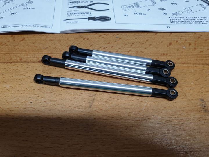
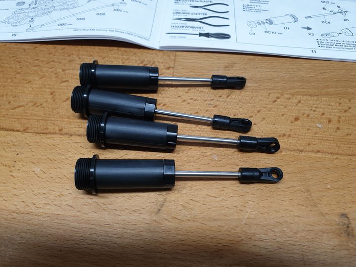
Dampers! Made out of bits.
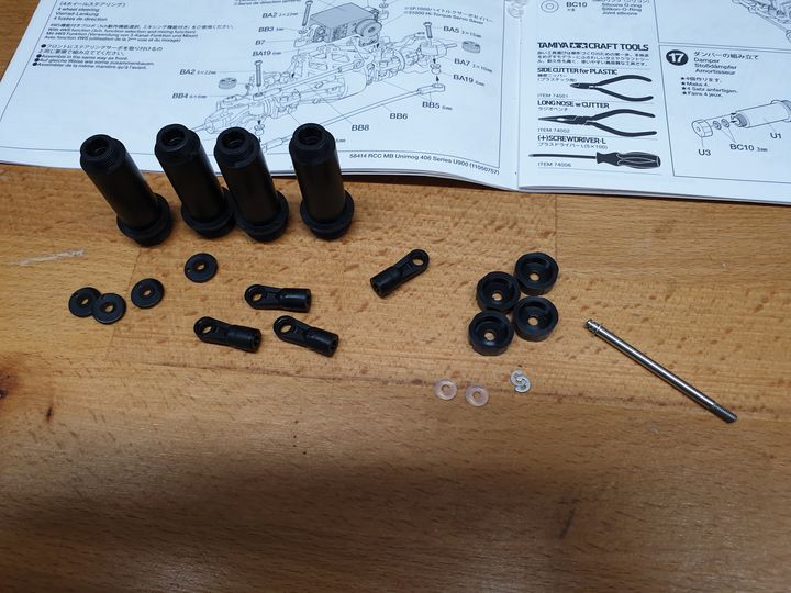
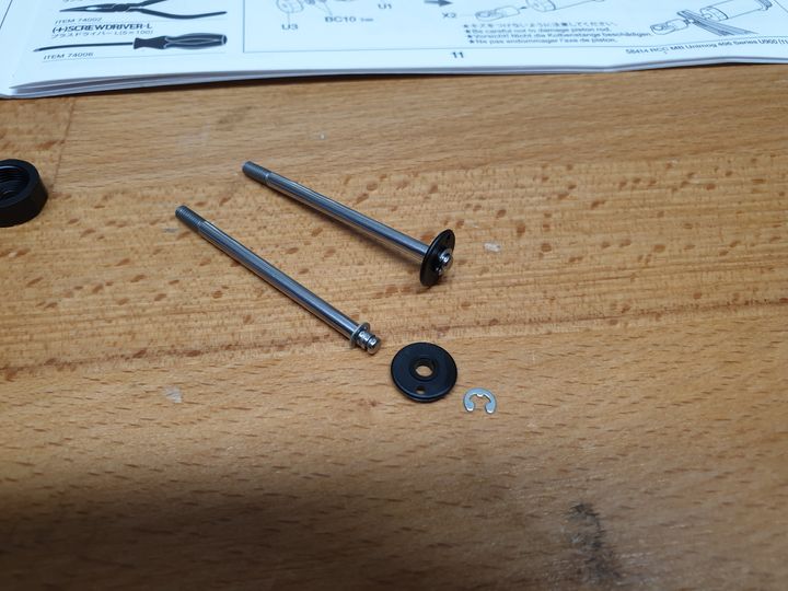
E-clip goes on the shaft, then the thingy that the thing things, then another E-clip.
Two O-rings get sandwiched into the damper body.
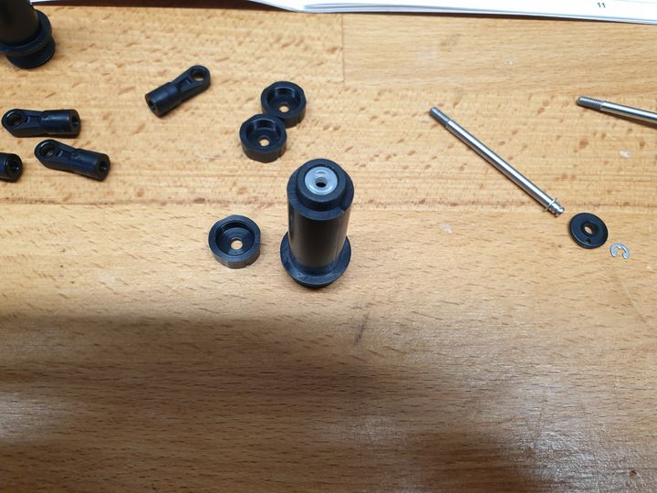
And then assembled ready for oil.
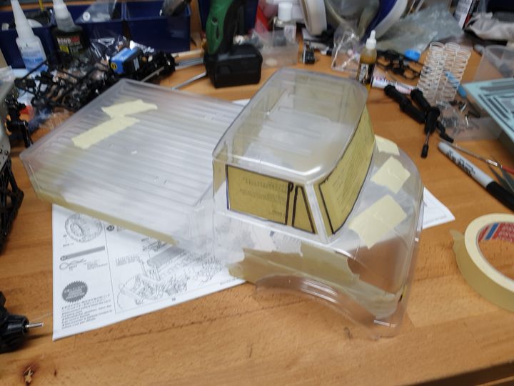
In the meantime I put the window and light masks on the body and covered the various holes on the outside.
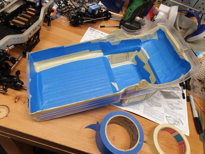
Then masked off the rest. Just the wheel arches and bumpers get black.
And the front axle in place. Leaving the rear until I've got the second servo saver.
Dampers! Made out of bits.
E-clip goes on the shaft, then the thingy that the thing things, then another E-clip.
Two O-rings get sandwiched into the damper body.
And then assembled ready for oil.
In the meantime I put the window and light masks on the body and covered the various holes on the outside.
Then masked off the rest. Just the wheel arches and bumpers get black.
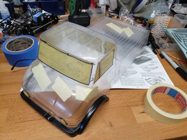
Black done, most of the masks removed.
First very light coat of green on. I've done three more and backed it in white since, so it'll have the rest of the day to cure before the window masks come off. Then the windows get two coats of smoke.
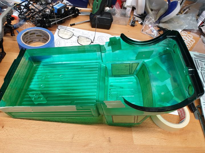
First very light coat of green on. I've done three more and backed it in white since, so it'll have the rest of the day to cure before the window masks come off. Then the windows get two coats of smoke.
Edited by Sporky on Tuesday 14th January 06:39
Gassing Station | Scale Models | Top of Page | What's New | My Stuff