Oddfire engine config for Haltech on an AJP8
Discussion


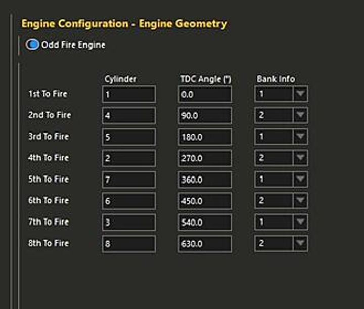
Good morning. I am currently installing a haltech nexus R3 on my TVR Cerbera. I need to configure the firing order and angles as shown below.
The engine is a 75 degree, flat plane crank V8. I know the firing order (as below) but im not sure how to go about configuring the angles. The angles in the table are currently just the default numbers from Haltech (presumably from an LS?)
Anybody have any ideas?
The engine is a 75 degree, flat plane crank V8. I know the firing order (as below) but im not sure how to go about configuring the angles. The angles in the table are currently just the default numbers from Haltech (presumably from an LS?)
Anybody have any ideas?
After a back-and-forth with my buddy ChatGPT about true piston TDC offsets, this is what we came up with.
"your firing order is evenly spaced (90°), yet the 75° bank angle + flat-plane geometry makes the cylinder TDC relationships uneven from the ECU’s perspective. That’s why Haltech needs it treated as odd-fire."
Because of the 75° V angle, you split the banks:
One bank gets +37.5°
The other gets –37.5°
That’s half the V-angle
So your actual ECU TDC inputs become:
Example (assuming Bank A = 1-3-5-7)
Cylinder Adjusted TDC
1 0° + 37.5° = 37.5°
4 90° – 37.5° = 52.5°
5 180° + 37.5° = 217.5°
2 270° – 37.5° = 232.5°
7 360° + 37.5° = 397.5°
6 450° – 37.5° = 412.5°
3 540° + 37.5° = 577.5°
8 630° – 37.5° = 592.5°
You could enter the base 90° table, and keep it in odd-fire mode. Then verify with timing light per cylinder, and adjust individual cylinder trims if you need to.
Kind of tuff to trust the theoretical geometry.
I would have thought that if you start with the right side bank, then after the crank has turned 90 degrees, it still has another 15 degrees to go for TDC on the left bank:
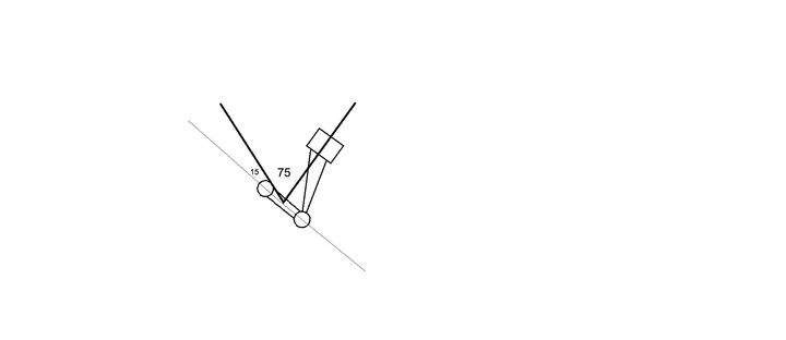
Then after left TDC, the crank only needs 75 degrees for the next right TDC, and so on.
So I would say it should be:
1: 0
2: 105 (+90 + 15)
3. 180 (+75)
4. 285 (+90 + 15)
5. 360 (+75)
6. 465 (+90 + 15)
7. 540 (+75)
8. 645 (+90 + 15)
This is assuming everything starts at 0 of course.
But I could be completely wrong
Edited by FarmyardPants on Friday 1st May 10:18
I cant help unfortunately with the crank angles but i do have a question. Why would you fit an ECU that hasn't been used on a cerb before when there are much better ECU's for a Cerbera that are already programmed for the job? Indeed there are also cheap options as well.
Genuine question.
Emerald
MBE
Motec
Syvecs
Genuine question.
Emerald
MBE
Motec
Syvecs
Don't know if this will be of any help, but from a post back in 2006 . . .
"The idle speed is around 1150rpm and I've noticed the ignition timing is about 14 degrees BTDC. I've read it should be around 17 degrees at idle."
https://www.pistonheads.com/gassing/topic.asp?h=0&...
So, between 14 and 17 degrees BTDC.
Then from "MBE 941 Ferrari V8 flat plane crank firing order", it is indicating that a good starting point is 20 deg BTDC.
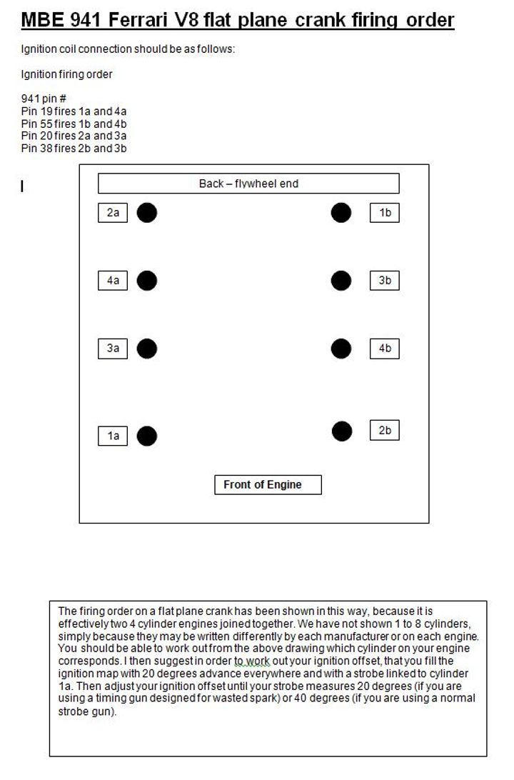
From this info it looks like a good starting point could be17 deg BTDC on cylinder 2. Of course you'll need to work out how that relates to the crank sensor position, but after that it should be easy to work out for each cylinder.
Hope that helps.
P.S. None of this was A.I. researched or generated. I wish people would stop posting that junk here.
"The idle speed is around 1150rpm and I've noticed the ignition timing is about 14 degrees BTDC. I've read it should be around 17 degrees at idle."
https://www.pistonheads.com/gassing/topic.asp?h=0&...
So, between 14 and 17 degrees BTDC.
Then from "MBE 941 Ferrari V8 flat plane crank firing order", it is indicating that a good starting point is 20 deg BTDC.
From this info it looks like a good starting point could be17 deg BTDC on cylinder 2. Of course you'll need to work out how that relates to the crank sensor position, but after that it should be easy to work out for each cylinder.
Hope that helps.
P.S. None of this was A.I. researched or generated. I wish people would stop posting that junk here.
itsallyellow said:
I cant help unfortunately with the crank angles but i do have a question. Why would you fit an ECU that hasn't been used on a cerb before when there are much better ECU's for a Cerbera that are already programmed for the job? Indeed there are also cheap options as well.
Genuine question.
Emerald
MBE
Motec
Syvecs
Mostly because I'm in Western Australia and finding someone to tune any of those would be difficult, if not impossible.Genuine question.
Emerald
MBE
Motec
Syvecs
The Haltech isn't crazy expensive and has a heap of features, and pretty much every tuner here can tune one.
The only issues are finding a timing table to start with (which I now have) and setting up the TDC crank angles as above.
All you need to do is set cyl 1 intake valve fully open. Put timing disc on front pulley and aim a pointer at the tdc mark. Cylinder 1 is zero degrees. Now rotate crank clockwise and note the sequence and timing that each successive inlet valve reaches full lift. That's your cylinder firing sequence and crank degrees of timing after the original cylinder 1 event.
spitfire4v8 said:
All you need to do is set cyl 1 intake valve fully open. Put timing disc on front pulley and aim a pointer at the tdc mark. Cylinder 1 is zero degrees. Now rotate crank clockwise and note the sequence and timing that each successive inlet valve reaches full lift. That's your cylinder firing sequence and crank degrees of timing after the original cylinder 1 event.
Yeah if I can't get it working that will be the solution. I'm not yet at the point of trying to start it yet.Is the firing order in the table correct? Pretty sure it is, but would be good to confirm.
I've been reverse engineering the mbe941 firmware as part of a restoration and learning exercise. I have a real mbe running on my bench with simulated signals.
I've also been working on building (with the aid of AI junk and emulator that can run our v8 firmware. The timings coming out of the emulator match (closely) the real signals as measured on a scope.
I dont have access to the real engine, so I don't know the angle of cyl 1 TDC with respect the crank signal sync pulse. "AI Bot" thinks its about 12 degrees - would be great if someone could confirm.
An example from real ecu: water temp 94, air temp 10, baro 1000. Seeing cyl 3+5 - 20.1ms and cyl 1+7 50.0ms. Both times are after the first tooth after the sync and 1000rpm
Ultimately, we are hoping to help configure a spare ECU "just in case"
Cheers
Mark
I've also been working on building (with the aid of AI junk
and emulator that can run our v8 firmware. The timings coming out of the emulator match (closely) the real signals as measured on a scope.I dont have access to the real engine, so I don't know the angle of cyl 1 TDC with respect the crank signal sync pulse. "AI Bot" thinks its about 12 degrees - would be great if someone could confirm.
An example from real ecu: water temp 94, air temp 10, baro 1000. Seeing cyl 3+5 - 20.1ms and cyl 1+7 50.0ms. Both times are after the first tooth after the sync and 1000rpm
Ultimately, we are hoping to help configure a spare ECU "just in case"
Cheers
Mark
Edited by Markb139 on Saturday 2nd May 10:32
Markb139 said:
I've been reverse engineering the mbe941 firmware as part of a restoration and learning exercise. I have a real mbe running on my bench with simulated signals.
I've also been working on building (with the aid of AI junk and emulator that can run our v8 firmware. The timings coming out of the emulator match (closely) the real signals as measured on a scope.
I dont have access to the real engine, so I don't know the angle of cyl 1 TDC with respect the crank signal sync pulse. "AI Bot" thinks its about 12 degrees - would be great if someone could confirm.
An example from real ecu: water temp 94, air temp 10, baro 1000. Seeing cyl 3+5 - 20.1ms and cyl 1+7 50.0ms. Both times are after the first tooth after the sync and 1000rpm
Ultimately, we are hoping to help configure a spare ECU "just in case"
Cheers
Mark
Well once I get this going I will have a spare ECU if you want it.I've also been working on building (with the aid of AI junk
and emulator that can run our v8 firmware. The timings coming out of the emulator match (closely) the real signals as measured on a scope.I dont have access to the real engine, so I don't know the angle of cyl 1 TDC with respect the crank signal sync pulse. "AI Bot" thinks its about 12 degrees - would be great if someone could confirm.
An example from real ecu: water temp 94, air temp 10, baro 1000. Seeing cyl 3+5 - 20.1ms and cyl 1+7 50.0ms. Both times are after the first tooth after the sync and 1000rpm
Ultimately, we are hoping to help configure a spare ECU "just in case"
Cheers
Mark
Edited by Markb139 on Saturday 2nd May 10:32
https://youtu.be/rVG6TPNcaDY?si=5-WwKA504BIhHv5Y
this link visualises the differences between cross and flat plane really well - I find it easier to understand as it shows how the exhaust pulses overlap which sucks power out of those cylinders in the cross plane configuration. Basically the cross plane configuration is seamless whereas crossplane has a hiccup at the end/start of each cycle.
I think the 15 deg adjustment mentioned above is absolutely the right technique to allow for the 75deg V angle. Just make sure that you get the big gap and small gap in the right places if that makes sense. This needs the cylinder numbering to be as per TVR i.e standing at the front of the engine bay, 1 front right and 2 is front left. The timing between pistons on the same crank pin (1 to 2) will always be the 90+15 and the timing between pistons on different crank pins (2 to 3) will always be 90-15
the whole pattern is offset by relative to TDC. FarmYardPants mentions it being higher on the ferrari - this is advance for the ignition spark i think, so dont need to worry about this yet.
Im finding AI is great to get within 80-90% of the right answer in seconds, but getting that final 20-10% right takes longer than just ignoring AI and figuring it out by myself!!!
Edited by Krog 4.5 on Friday 8th May 11:30
Edited by Krog 4.5 on Friday 8th May 11:54
PLEASE NOTE THIS TABLE IS NOW KNOWN AS INCORRECT BUT ILL LEAVE IT HERE TO SHOW THE JOURNEY OF THE CONVERSATION.... ITS INCORRECT BECAUSE I ASSUMED THE CRANK PINS WENT UP DOWN UP DOWN. THE CRANK IS UP DOWN DOWN UP... NEW DIAGRAM IS LOADING CHECK FURTHER DOWN THE THREAD
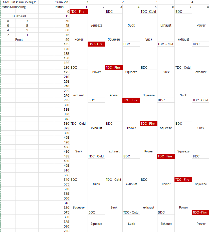
Theres a table of how I think it works... I've listed the Cylinder numbers and the firing order. Note you can follow the Up-Down-Up-Down on the crank pin numbers and TDC BDC... you can read the firing angles off this and put into your ECU
On the Cylinder firing order I would change them to read consecutively from 1-8. i.e. First to fire: cylinder 1, Second to fire: cylinder 2... etc
Edited by Krog 4.5 on Friday 8th May 12:01
Edited by Krog 4.5 on Friday 15th May 08:42
Krog 4.5 said:
https://youtu.be/rVG6TPNcaDY?si=5-WwKA504BIhHv5Y
this link visualises the differences between cross and flat plane really well - I find it easier to understand as it shows how the exhaust pulses overlap which sucks power out of those cylinders in the cross plane configuration. Basically the cross plane configuration is seamless whereas crossplane has a hiccup at the end/start of each cycle.
I think the 15 deg adjustment mentioned above is absolutely the right technique to allow for the 75deg V angle. Just make sure that you get the big gap and small gap in the right places if that makes sense. This needs the cylinder numbering to be as per TVR i.e standing at the front of the engine bay, 1 front right and 2 is front left. The timing between pistons on the same crank pin (1 to 2) will always be the 90+15 and the timing between pistons on different crank pins (2 to 3) will always be 90-15
the whole pattern is offset by relative to TDC. FarmYardPants mentions it being higher on the ferrari - this is advance for the ignition spark i think, so dont need to worry about this yet.
Im finding AI is great to get within 80-90% of the right answer in seconds, but getting that final 20-10% right takes longer than just ignoring AI and figuring it out by myself!!!
Thanks for backing up my logic, although the Ferrari bit wasn’t me this link visualises the differences between cross and flat plane really well - I find it easier to understand as it shows how the exhaust pulses overlap which sucks power out of those cylinders in the cross plane configuration. Basically the cross plane configuration is seamless whereas crossplane has a hiccup at the end/start of each cycle.
I think the 15 deg adjustment mentioned above is absolutely the right technique to allow for the 75deg V angle. Just make sure that you get the big gap and small gap in the right places if that makes sense. This needs the cylinder numbering to be as per TVR i.e standing at the front of the engine bay, 1 front right and 2 is front left. The timing between pistons on the same crank pin (1 to 2) will always be the 90+15 and the timing between pistons on different crank pins (2 to 3) will always be 90-15
the whole pattern is offset by relative to TDC. FarmYardPants mentions it being higher on the ferrari - this is advance for the ignition spark i think, so dont need to worry about this yet.
Im finding AI is great to get within 80-90% of the right answer in seconds, but getting that final 20-10% right takes longer than just ignoring AI and figuring it out by myself!!!
ah yes sorry I was skim reading!! yes I think the + - 15 deg is the way to go. Approached it from a different angle (pardon the pun!) to see if I could get the same answer... all adds up.
Im tempted to write out the same diagram for a X plane now cuz I think it'll look awful as the firing order jumps around so much. I think this is one of the reasons why flat plane cranks can be much lighter as the stress is loaded up in a way that kind of twists it and maintains the tension like a watch spring, whereas the X plane is twanging the Crankshaft from pin 1 then pin 4 etc etc. The changes in stress on the X plane would lead to earlier cyclic stress failures.
Kinda wish the AJP8 was a 90deg though.... I think the + and - 15 deg is what gives the AJP8 its distinct exhaust note... I had a two V twin motorbikes, a ducati 916 and then a KTM superduke when I was a young man... they were 90 deg and 75 deg respectively. The ducati sounded deep and ever so sweet, like a tuned V8 however the KTM was equally deep but so angry sounding. Im sure that was because of the V angle
Edited by Krog 4.5 on Friday 8th May 13:14
Indeed! this does makes sense as I also wondered why a flat plane crank (excellent for high revs) was paired with 2 valves per cylinder (low revs, lazy torquey)... the obvious combination is a 4 valve per cylinder to allow highest air flow. I think this was also chosen to make the heads more compact as it only needs one camshaft per head. I've asked Al Melling but hes not answered!! Might be a touchy subject
There is a video floating around where Al explains the design decisions. Can t find it after a perfunctory search but IIRC it s to do with torque and drivability. He was worried that it would be too peaky, even overkill with 4 valves per cylinder. But there were probably also cost considerations for the valve train, stronger conrods etc. Also perhaps reliability as it was designed as a race engine. To be fair the AJP itself is a pretty reliable thing given its racing aspirations.
Edited by FarmyardPants on Friday 8th May 17:56
Krog 4.5 said:
Theres a table of how I think it works... I've listed the Cylinder numbers and the firing order. Note you can follow the Up-Down-Up-Down on the crank pin numbers and TDC BDC... you can read the firing angles off this and put into your ECU
On the Cylinder firing order I would change them to read consecutively from 1-8. i.e. First to fire: cylinder 1, Second to fire: cylinder 2... etc
Edited by Krog 4.5 on Friday 8th May 12:01
FarmyardPants said:
There is a video floating around where Al explains the design decisions. Can t find it after a perfunctory search but IIRC it s to do with torque and drivability. He was worried that it would be too peaky, even overkill with 4 valves per cylinder. But there were probably also cost considerations for the valve train, stronger conrods etc. Also perhaps reliability as it was designed as a race engine. To be fair the AJP itself is a pretty reliable thing given its racing aspirations.
I'd love to see that if you ever find the video!Edited by FarmyardPants on Friday 8th May 17:56
Gassing Station | Cerbera | Top of Page | What's New | My Stuff