MEV Sonic7 Build "First Engine Run"
Discussion


Achieved first engine run today  after just 7 weeks into the build, so the next major milestone will be to fit the bodywork and put her on her wheels.
http://uk.youtube.com/watch?v=5f_Nb9cu0_I
(If you'd like to know more visit my Web Site www.mevsonic7.co.uk)
after just 7 weeks into the build, so the next major milestone will be to fit the bodywork and put her on her wheels. http://uk.youtube.com/watch?v=5f_Nb9cu0_I
(If you'd like to know more visit my Web Site www.mevsonic7.co.uk)
Edited by Sonic7 on Saturday 17th January 09:57
Sonic7 said:
Achieved first engine run today after just 7 weeks into the build, so the next major milestone will be to fit the bodywork and put her on her wheels.
http://uk.youtube.com/watch?v=5f_Nb9cu0_I
(If you'd like to know more visit my Web Site www.mwvsonic7.co.uk)
Hi Nigel, that is a great achievement, how long did it take you to reach this stage? how manu hours for the build ? after just 7 weeks into the build, so the next major milestone will be to fit the bodywork and put her on her wheels. http://uk.youtube.com/watch?v=5f_Nb9cu0_I
(If you'd like to know more visit my Web Site www.mwvsonic7.co.uk)
Looking forward to your update.
Cheers
Italo
robcollingridge said:
In this pic  , I can't see how the balance bar would work. It looks to be in compression from the sides?
Hi Rob. Rather than put an explanation into words visit the following site where all will be revealed., I can't see how the balance bar would work. It looks to be in compression from the sides?http://www.rallydesign.co.uk/catalog/balancebar.ph...
Geoff.
Yes, I've seen that page before and it supports the point I'm making. In the bottom right picture shown on the linked page, there is a gap A and B, which is required in order to allow the mechanism to function as designed.
From what I can see in the photo (though I admit it might just be the angle the picture was taken), the two washers either side of the pedal look like they have no gap either side of them and are clamped tightly against the pedal body. They need to have a gap either side and some sideways movement or the bias bar will be clamped at 90 degrees to the pedal and won't work.
Tell me if I've interpreted the photo wrongly though.
Rob
robcollingridge said:
Yes, I've seen that page before and it supports the point I'm making. In the bottom right picture shown on the linked page, there is a gap A and B, which is required in order to allow the mechanism to function as designed.
From what I can see in the photo (though I admit it might just be the angle the picture was taken), the two washers either side of the pedal look like they have no gap either side of them and are clamped tightly against the pedal body. They need to have a gap either side and some sideways movement or the bias bar will be clamped at 90 degrees to the pedal and won't work.
Tell me if I've interpreted the photo wrongly though.
Rob
Great to see there are some eagle eyed builders out there. You are correct, the gaps are not set correctly in the picture, you may also notice that the pedal box is not fully bolted in position either. The key point of this picture in the build is to show the position of the holes that are required to be drill in the balance bar (best done on the bench prior to installation) inorder to insert roll pins to lock out the adjustment capabilities for SVA purposes.From what I can see in the photo (though I admit it might just be the angle the picture was taken), the two washers either side of the pedal look like they have no gap either side of them and are clamped tightly against the pedal body. They need to have a gap either side and some sideways movement or the bias bar will be clamped at 90 degrees to the pedal and won't work.
Tell me if I've interpreted the photo wrongly though.
Rob
REF SVA Rules:-
"2. Roller Brake Test
A vehicle that incorporates an adjustment device
(eg pedal linkage balance bar) that adjusts the
front/rear braking ratio (longitudinal brake
distribution) must be tested in the “worst case”
condition, ie maximum rear axle braking.
NOTE: Devices that allow further adjustment, eg
lock nuts/adjustable stops/split pins, will not, in
isolation be considered as capable of preventing
further adjustment to a "worse" condition. (A roll
pin will be considered accetable)"
Please be assured that the correct settings in line with the manufactures recommendations will be adheard to prior to both road and brake testing at my local garage with the balance proably ending up favouring the rear as i'm using Wilwood 4 pistion on the front and standard focus on the rear with a weight distribution of approximatly front/rear 40/60 on 500kg.
Once tested to ensure SVA compliance with the rules I will space out accordingly and role pin prior to SVA.
Like your site Rob
Nigel
Edited by Sonic7 on Saturday 17th January 20:51
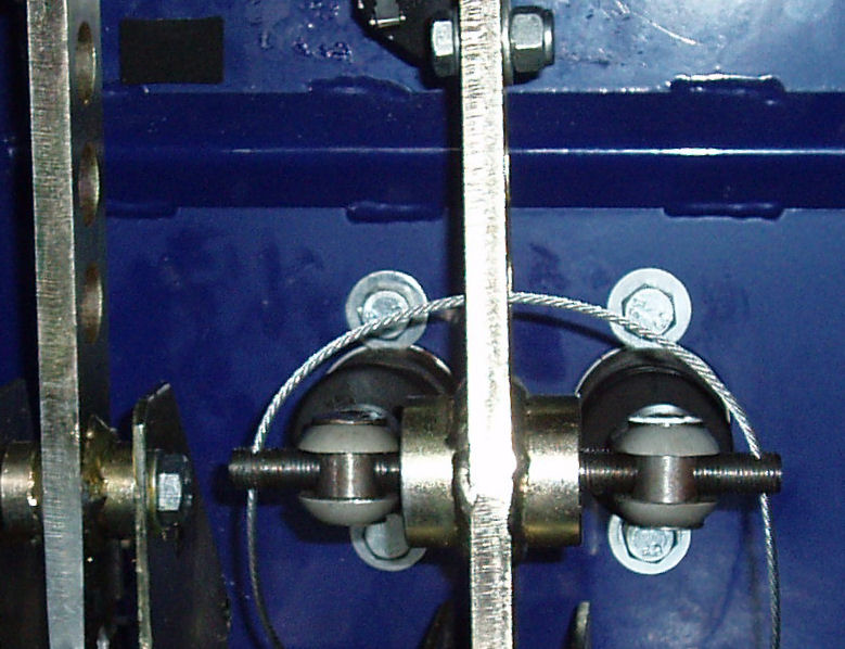
Cool. One way easy way to lock the balance bar is to run some stiff wire between the two holes you have drilled (behind the brake pedal) and bend the ends once through the holes. If you have a whole in the brake pedal to pass it through, then even better.
This is what I've done in my Fury (though the cable shown has been cut down since I took this picture). It's a lot easier than trying to fiddle with spacer washers and drilled bolts.
Rob
This is what I've done in my Fury (though the cable shown has been cut down since I took this picture). It's a lot easier than trying to fiddle with spacer washers and drilled bolts.
Rob
robcollingridge said:
Cool. One way easy way to lock the balance bar is to run some stiff wire between the two holes you have drilled (behind the brake pedal) and bend the ends once through the holes. If you have a whole in the brake pedal to pass it through, then even better.
This is what I've done in my Fury (though the cable shown has been cut down since I took this picture). It's a lot easier than trying to fiddle with spacer washers and drilled bolts.
Rob
Rob,was that accepted by the sva tester ?This is what I've done in my Fury (though the cable shown has been cut down since I took this picture). It's a lot easier than trying to fiddle with spacer washers and drilled bolts.
Rob
I didn't try this route for the SVA test but, I can't see what the problem would be so long as the wire ends are unable to come loose. As it is, there is a tiny amount of rotation possible on the balance bar (say 5 degrees) but this is not enough to alter the braking balance. On one end of the cable is the cable nipple and on the other I had a small clamping bolt.
My main reason for doing this post-SVA was to make it easier to change the brake bias as the brakes bedded in. It is also a much simpler and lighter way to do it and I was saving weight when ever possible. The footwell on a Fury is not the easiest thing to reach, once the seats are in. There is an access cover above the footwell but it is not really big enough to get two hands through at the same time.
My main reason for doing this post-SVA was to make it easier to change the brake bias as the brakes bedded in. It is also a much simpler and lighter way to do it and I was saving weight when ever possible. The footwell on a Fury is not the easiest thing to reach, once the seats are in. There is an access cover above the footwell but it is not really big enough to get two hands through at the same time.
Gassing Station | Kit Cars | Top of Page | What's New | My Stuff