Reference voltage drops when engine runs?
Discussion


I've managed to work out why my car is running rich, but I'm looking for some wisdom to help figure out th root cause of the fault.
I have an '02 TVR tamora, which as standard uses an MBE ecu with throttle pot led mapping. From the diagnostic software (ignition on, engine not running), I can see that all sensors are working fine, that the t-pots (x2 banks of cylinders) are set up and that they respond just as they should right through the throttle travel. However, as soon as the engine is started, the t-pot readings both shoot up from about 10% on idle to 30% on idle. After much head scratching, and a bit of help, I've found out that the 5v refernce voltage that feeds the t-pots drops to about 4.3v when the engine runs, meaning the tpot output is skewed proportionally.
So, question is, before I just assume that my mbe ecu is at fault (an if I is, it's the first fault of it's kind known to mbe) then what else could be causing this voltage drop? What actually changes elecrically when the engine starts running?
Thanks in advance, rob.
fatjon said:
Check the voltage between the battery ground post and the TPS ground at the TPS. This will tell you if the TPS5v reference is dropping or the ground is floating higher. If it's the latter you have an bad ground somewhere. Where that somewhere is will be a challenge though.
The other resistive sensors use the same ground as the tpots however, and since their readings are unchanged when the engine runs, is it not possible to rule out this possibility?Seriously though, thanks for the suggestions chaps- it all helps.
Aside: Hows the cerbomega coming on Jon?
brogenville said:
fatjon said:
Check the voltage between the battery ground post and the TPS ground at the TPS. This will tell you if the TPS5v reference is dropping or the ground is floating higher. If it's the latter you have an bad ground somewhere. Where that somewhere is will be a challenge though.
The other resistive sensors use the same ground as the tpots however, and since their readings are unchanged when the engine runs, is it not possible to rule out this possibility?Seriously though, thanks for the suggestions chaps- it all helps.
Aside: Hows the cerbomega coming on Jon?
The earth is rising!!!
As reccomended to me on here, I put the voltmetre across the ground termainl on the tpot plug and the engine block: 6.5mV with engine off (which is easily just the error in my cheap digital multimetre), but a whopping 0.4V with the engine on. in fairness, this doesnt totally explain why the voltage read across the 5V Vref and Tpot ground drops by up to 0.7V, but its certainly of note.
Secondly, and I'm ashamed not to have picked up on this before, but the air and water temps read on the laptop both drop by about 6 degrees when the engine is started, and looking at the wiring diagram, they both use the same ground as the tpots.
Thirdly, i notice that the reading on the baro sensor doesnt budge when the engine is started, and seemingly this uses the same 5V Vref as the tpots.
Sooooooo... could I just have a bad earth? An earth which grounds the engine bay sensors, but not the baro sensor in the cabin???
[I'm quite glad that its looking slightly less likely that I wont need a new ECU. smile ]
Been spending the last few hours checking different grounds. Sadly, everything looks sound (though everything got cleaned up as I went anyway). ICuriously, the main ground to the ecu did have to come off when I changed the clutch recently. Truth is, when I put everything back together with the clutch fitting, I couldn't remember exactly which bolt held this wire on, so I just bolted it on with one of the starter motor bolts. I can't imagine this would matter though, since any induced voltage the starter could cause would stop as soon as the starter stops (though I guess there will be a fairly hefty magnet in the starter solenoid)?
See picture below for where I have the ecu ground connected to:
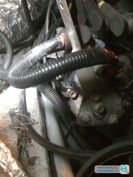
Is it possible that a connection to this ground inside the loom could be corroded, meaning when the engine starts running, and the ecu starts using more current, it struggles to get a stable ground? There was a post recently where someone traced an injector fault to corrosion inside the sealed loom on a similar car.
Gonna have to keep scratching my head!
See picture below for where I have the ecu ground connected to:
Is it possible that a connection to this ground inside the loom could be corroded, meaning when the engine starts running, and the ecu starts using more current, it struggles to get a stable ground? There was a post recently where someone traced an injector fault to corrosion inside the sealed loom on a similar car.
Gonna have to keep scratching my head!
Damn I'm good!
Easy fix, not the most elegant but easy. Get a clean, good earth from the block and splice it into the TPS earth very close to the throttle pot, thus bypassing the dodgy earth somewhere in the loom between the pot and where it picks up its earth. Functionally identical circuit but saves you finding what could be a very obscure fault. Having had a quick scan of the wiring diagram the 3 TPS wires all end at the ecu so it picks up its earth there but it goes through some splices first. It may be worth checking at the ECU if it's earth rises in which case the problem is with the major earth to the ECU, this seems less likely though as this would surely upset a whole lot of systems and sensors. Either way the little bodgette will fix the problem.
Easy fix, not the most elegant but easy. Get a clean, good earth from the block and splice it into the TPS earth very close to the throttle pot, thus bypassing the dodgy earth somewhere in the loom between the pot and where it picks up its earth. Functionally identical circuit but saves you finding what could be a very obscure fault. Having had a quick scan of the wiring diagram the 3 TPS wires all end at the ecu so it picks up its earth there but it goes through some splices first. It may be worth checking at the ECU if it's earth rises in which case the problem is with the major earth to the ECU, this seems less likely though as this would surely upset a whole lot of systems and sensors. Either way the little bodgette will fix the problem.
Went with your suggestion Jon. Ecu earth has now been relocated, and I've spliced in two new earths to the ground signal on each of the tpots (right behind the sensors themselves) that earth at the same ecu earth location. Very frustrating that I don't know what the real cause of the problems are, but the good news is that all the sensors now how the same readings with the engine on or off. The bad news is that all the over-fueling has buggered the lambda sensors, so I've ordered a couple of new ones this evening.
I really cant thank everyone enough for the helpful advice.
Rob.
I really cant thank everyone enough for the helpful advice.
Rob.
Oh cock. I put some new lambda sensors in last night and try as i might, the little blighters just would not give me a cylic ~1V output. There is something happening with them, as the old ones sat dead on 0.01V constantly, whereas the new ones manage to show a heady 0.08 - 0.1 V. So, it would would probably be reasonable to assume that the rising voltage that offset the tpots is having the same effect on the lambdas, except that its more noticible on the lambas where the output voltage is much lower. That might be fine- shouldnt be too hard to add new earths here too back to the "new" ecu earth I've made (although this solution is getting more and more messey). However, and perhaps I've stumbled on the cause of my problems... when I tested the continuity of the 4 terminals on the lambda plugs, on both of lambdas 3 of the 4 terminals showed continuity with ground! Now, as I understand it, the lambda connections are:
1) Black wire on TVR loom (grey wire on sensor) = additional earth for lambda signal
2) Black wire on TVR loom (white wire on sensor) = lambda heater
3) Red wire on TVR loom (other white wire on sensor) = lambda heater
4) Yellow wire on TVR loom (black wire on sensor) = lambda signal
I find that 1, 2, and 3 are all showing earth continuity. This is fine for 1 and 2, but shouldn't 3 be 0V with ignition off, and a constant 12V as soon as ignition is on? If this wire has been grounded somewhere, then perhaps the 12V supply for the lambda heater is whats bringing the ecu ground up?
I might test out this theory by pulling the fuse for the lambda heaters, but in the mean time, any thoughts anyone has would be appreciated.
Another update for the keyboard warriors out there...
I'm sure that there is something wrong with the lambda heater supply connection showing earth, so I had a go at tracing it back. Unplugging the big bulkhead connector I found that on the loom side there was no earth to this wire, so the fault was not with the engine bay loom. Sadly however, the connector seems to come out behind the middle of the dash, making further wire tracing very difficult. Even with taking the dsah binnicle out, its impossible to get to. I suppose the only way would be to remove the centre dash section, but I couldn't quite bring myself to that last night.
I did have a go however at starting the car witht the lambda heater fuse removed. Since the heater is only there to give a faster heat up from cold, and many lambda sensors do without this, it seemed worth while. What I found though only boggles the mind further. When I first started it up, I got a little twitch from the lambda voltages, but (with a very reluctant engine) I managed to get up to tempreature, and slowly one of the lambdas started to show a higher voltage. "Excellent" or so I thought, as gradually it became apparent that one of the lambdas was still on 0.01V, and the other was just becoming stuck at about 1.8V. Given that this is potentially a symptom of wrongly connected lambdas, I switched off and swapped them round. Starting up again... exactly the same thing, but with opposite lambdas high and low.
I'm getting quite tired of this now.
How many wires do the sensors have ?
And again, does your ecu even use the sensors ?
If you are just trying to use the sensor to give YOU some feedback, and not the ecu, just disconnect them totally from the car. Chances are they will never get up to temperature with no heater when sitting at idle, but they will work once you start driving.
The sensors are the 4 wire zirconia type, which apparently shows a low voltage in the presence of oxygen (lean conditions). The MBE ecu on the TVR's runs closed loop up to 4500 rpm with the ability to adapt the base map up to +/- 37% according to the lambda conditions. So, the data I was seeing on the laptop isn't just for viewing purposes- I could physically see the ecu adapting the map (up to its limit).
I sort of believe you about the lambdsas not comking up to temp, as they didnt really show much untill I gave it quite a bit of revs.
I sort of believe you about the lambdsas not comking up to temp, as they didnt really show much untill I gave it quite a bit of revs.
Right, the bloody thing is completely undriveable, and even with me cleaning the plugs up (3 of which showed evidence of lean running, 3 of rich running) it basically won't run anywhere below 3-4krpm. It needs loads of throttle to even start and more to stay running. It though perhaps it wasn't sparking properly at low revs, but a test with the plugs out show them sparking strongly. Short of throwing a match at it, I'm sending the ecu off tomorrow to someone who can test it in a known working car.
Why did it run faultlessly all through the winter only to fail me when the sun comes out!!!?
Why did it run faultlessly all through the winter only to fail me when the sun comes out!!!?
brogenville said:
The sensors are the 4 wire zirconia type, which apparently shows a low voltage in the presence of oxygen (lean conditions). The MBE ecu on the TVR's runs closed loop up to 4500 rpm with the ability to adapt the base map up to +/- 37% according to the lambda conditions. So, the data I was seeing on the laptop isn't just for viewing purposes- I could physically see the ecu adapting the map (up to its limit).
I sort of believe you about the lambdsas not comking up to temp, as they didnt really show much untill I gave it quite a bit of revs.
MBE is an aftermakret ecu. So may or may not run closed loop depending on who programmed it.I sort of believe you about the lambdsas not comking up to temp, as they didnt really show much untill I gave it quite a bit of revs.
And nobody in their right mind would ever give a narrowband sensor a window of 37% correction !!!! nevermind +/- 37% !!! that is just ridiculous given narrowband sensors are only accurate at 14.7:1
3.7% maybe, but not 37.
And rather than posting the ecu off, it would make more sense to take car and ecu to someone capable of diagnosing the problem.
Appreciate your comments steve; I'm informed that the ecu does run closed loop below 4500rpm by a well regarded tvr mapper, so I've no reason to disbelieve. With the +/- 37 % I was in fairness just referring to the adaptive values shown on the diagnostic software, which I assumed were percentage, but now you mention it, that does seem excessive.
At this point I would happily pay for someone to fix the car, but I'm in Aberdeen, and there really isn't anyone in Scotland that knows anything about mbe ecus (I'll be happy to learn otherwise though). Doesnt Posting off the ecu for q quick and inexpensive test seems pretty reasonable at this point?
At this point I would happily pay for someone to fix the car, but I'm in Aberdeen, and there really isn't anyone in Scotland that knows anything about mbe ecus (I'll be happy to learn otherwise though). Doesnt Posting off the ecu for q quick and inexpensive test seems pretty reasonable at this point?
Gassing Station | Engines & Drivetrain | Top of Page | What's New | My Stuff