2013 Ferrari FF
Discussion


200Plus Club said:
Are you in the Sheffield area by any chance as a pal spotted a blue one at the tip recently doing a tip run, very impressive if its you!
Nope not me, a bit further North than Sheffield but I have done a tip run or two!Wills2 said:
I must admit the brake bolts would be bothering me, I'd prefer to have lived in ignorance, need to be sorted can't have a car with that performance without being able to smash the brake pedal with confidence, I'd be stumping up for a new set.
Yep that's the way I'm leaning.I've had a response today from rebrake.de. This is a German company that resurface CCBs for various marques. They can, and do supply the fixings and their price is 450Euros per ten needed for each disc.
It's an insane amount of money for 10x bolts, but honestly it's sounding like a way to just buy my way out of some stress and just get it sorted.
Fonzey said:
Yep that's the way I'm leaning.
I've had a response today from rebrake.de. This is a German company that resurface CCBs for various marques. They can, and do supply the fixings and their price is 450Euros per ten needed for each disc.
It's an insane amount of money for 10x bolts, but honestly it's sounding like a way to just buy my way out of some stress and just get it sorted.
At that price, the temptation to get a big order made up yourself and become a defacto supplier of these things must be huge! Become the ‘MrVanos’ of Brembo Carbon Ceramic Bolts - get yourself on all the forums and Facebook groups I've had a response today from rebrake.de. This is a German company that resurface CCBs for various marques. They can, and do supply the fixings and their price is 450Euros per ten needed for each disc.
It's an insane amount of money for 10x bolts, but honestly it's sounding like a way to just buy my way out of some stress and just get it sorted.

I said I'd write later about the bolts themselves, or what I can find out about them. Now is "later"! This is probably rather nerdy for the average FF enthusiast, so feel free to ignore it and skip on by to more fun topics 
Unbelievably (given the length of this post about a simple bolt), I'm skipping over some things, and simplifying others. I'm sure true bolted joint experts will be able to jump in and pick me up on them. Forgive me those; it is a long time since I designed a bolted joint in detail, and I'm trying (and probably failing) to make this at least mostly accessible to a nerdy generalist audience!
These are probably stretch bolts that are being tightened using torque+angle to put the bolt into plastic deformation.
This is done to maintain the clamping load on the disc as the bolt shortens and lengthens as the temperature hits it.
You can imagine the ceramic has a really low coefficient of thermal expansion and the bolt, despite the added titanium, will expand a lot more. In an extreme case, the bolt could expand so much, that there is no longer any clamping force on the disc.
Putting the bolt into plastic deformation should mean that the clamping force changes much less as the temperature changes, as the force now moves back and forth on the flat part of the curve.
You won't be able to do this with your Halfords torque wrench.
My first thoughts were that these bolts should be treated as consumables and regularly replaced, but I now think it is not quite so simple as I initially thought.
Of course, I could have this completely back-to-front.I could also be wrong but surely in order to maintain clamping pressure you want to use the elastic zone of the material. Once you are into the plastic zone, higher stress means more plastic deformation and therefore loss of clamping pressure when you remove the stress.
pre-loading the fasteners to a set torque is to protect them from fatigue loading normally??Questions about torque-to-yield fasteners / "stretch bolts" come up from time to time. Here's my attempt at explaining what they're about.
Most joints change. Gaskets shrink. Components expand and contract with heat (including bolts themselves). Every component adds weight and cost.
In designing a bolted joint, the questions are broadly:
(a) how do I get the maximum clamping force from the minimum-sized component; and
(b) how do I get the minimum change in clamping force from my fastening with any change in the geometry of my joint; and
(c) how do I minimise fatigue issues; and
(d) how do I get the most consistently-installed clamping force?
(a) is easy - if the bolt is at (or very close to) yield, that's the maximum clamping force you can get from that bolt (well, almost - see below). So a torque-to-yield fastener is going to give us the maximum force for that size of fastener.
(b) is geometrical. Let's consider two bolts, of diameter 6mm and 8mm. We want a clamping force equivalent to a load in the bolt of 8kN.
At 8kN, our two bolts both stretch. Let's say (numbers made up for illustration) that at 8kN load, we find:
- our 6mm bolt stretches 1.8mm
- our 8mm bolt stretches 0.8mm
Let's assume (to make the illustration easier to visualise) we have a gasket in our joint. Let's say it was 1.2mm when installed, and that it relaxes under load by 25% - a net loss of 0.3mm.
Either bolt will pull the joint closed. But in the elastic region, a reduction in strain (stretch) will be proportional to a reduction in load in the bolt. So:
- our 6mm bolt loses 0.3/1.8 of the load, leaving 6.7kN
- our 8mm bolt loses 0.3/0.8 of the load, leaving 5kN
Therefore using an 8mm bolt in place of a 6mm bolt gives us a variation in clamping force (in response to gasket relaxation) of 38%, vs only 16% for the 6mm bolt.
So that's why we want the smallest bolt possible, which means it has to be tightened to at - or very close to - yield.
(c) is all to do with S-N curves - where "S" is the stress range (i.e. max-to-min load) and "N" is the number of cycles to fatigue failure. Higher "S" gives lower "N" to fatigue failure (very broadly). Since our torque-to-yield fastener has (by the calculations above) the smallest possible change in load with joint geometry changes, so "S" is minimised, to the benefit of "N."
Obviously it is more complex than that - there's also a stress endurance limit, which is the stress range below which no damage occurs in the face of cyclical load, but we're going to assume for a thin-as-possible bolt we don't get to choose to be below the endurance limit. If we wanted to ensure no fatigue were possible then we'd go with either a different joint design, or a much fatter joint and handle the load-changes differently.
Engineering is usually about compromises
(d) is about making sure we can predict the clamping force after installation. Assuming we're going to "torque" the joint with a socket / spanner (and not with some sort of hydraulic tensioning rig), we have to relate what we can measure at-the-spanner to the load in the bolt.
In the old days, we used to just apply a measured torque. The problem is that torque ("torque it up to XX Nm") isn't just clamping: it is also overcoming friction (under the bolt head, in the threads, etc.). If you lubricate a bolt before torquing, the clamping force can be way, way higher than if you don't, for instance. In extremis, you can torque up a well-oiled bolt "to spec" and have it snap before it get to the spec torque.
That's not good, because it doesn't allow proper - predictable - control of the clamping force. And it is - usually - the clamping force we're worried about.
There's another way to do that - "torque angle" - where you do up the bolt a bit (say 5 Nm, just enough to know you're now building load in the bolt, i.e. the joint is "done up" at a basic level), and then tighten by *angles*. Because the thread pitch is known, as are the other dimensions, a known angular deflection will give rise to a known strain (stretch) and therefore a known clamping force - because, assuming the material of the bolt is still in the elastic region, stress and strain will be perfectly correlated in a predictable fashion.
But even a "torque angle" approach doesn't guarantee the clamping force; it just attempts to control for one variable. It is still very hard to get things to the point of a consistent fastener load.
What would be great is if we could torque it up to yield, and do so reliably. That's made much easier by the shape of the stress-strain curve. The yield point isn't the start of the flat-topped curve everyone imagines. There is plastic deformation, but (to start with) the bolt can still carry more load. It is just that the stress-strain curve has flattened out. Strain hardening means the bolt can continue to carry more load (for a while), but the deformation is permanent. This is why torque-to-yield is so handy - you can get to the yield point, and go a little bit further, and the load will level off - you get a much more accurate bolt pre-load, whilst also reducing the clamp load variability (as above).
Here's a simplified diagram somebody else drew:
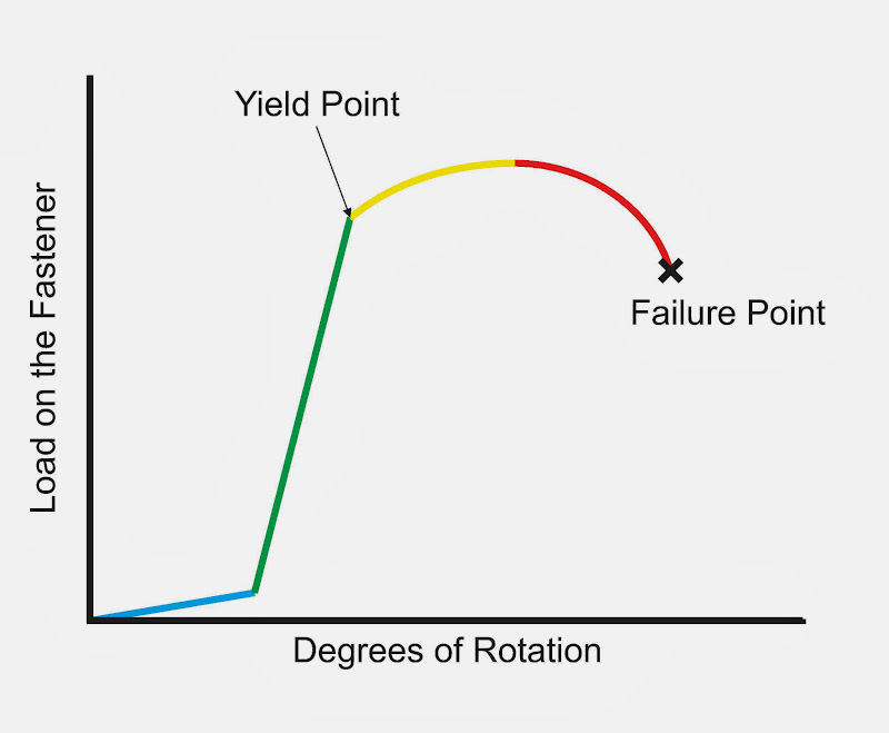
So our tightening becomes much easier - we just need to get past yield, and not far enough to go "over the hump." As you can see from the flattening, it just a much bigger area to aim for when measuring in "how many degrees of rotation to yield."
OK, so all of that's fine. But surely, if the bolt is tightened to yield, how can it carry increased loads (thermal stress, cyclic stresses, etc.) without just plastically deforming?
First, there's post-torquing settlement of the joint. The materials in the fastener and interface stacks will never be perfectly smooth, perfectly aligned, and so on. The threads will be imperfect, and there's a fair degree of friction (in a conventionally-torqued bolt, as much as 1/3 of the applied torque results in torsional stress in the bolt, not axial load) - but with a bit of time, that torsional stress will relax a touch. In the old days, it was said one should torque up a bolt, leave it for a while, hit the whole assembly with a large hammer, and then re-torque it
So in the real world, there will often be a slight reduction in bolt tension after tightening. That provides a (very small) portion of elastic region remaining to accommodate any slight stress increases. That's almost always sufficient. Remember, once we've reached yield, the stress-strain curve for removal of load isn't a reverse down the yield slope; it is an elastic relaxation (steep curve) from the end of tightening. So the joint settlement will leave us with a very small elastic window of operation.
In many gasketed joints, the effect is much more pronounced, as per the calculation above. The bolt relaxes down the elastic stress-strain curve quite a bit, but we're still left with a predictably-consistent clamping load across multiple bolts (important in our CCM brake disc).
That's one of the reasons you should never re-use compressible gaskets if you can avoid it, BTW.
Obviously in these CCM discs, it is the nut that is torqued, not the bolt / machine screw, and the under-head friction is likely to be pretty low (between the "wafer" head and the CCM material), but the principle still applies even if on a smaller scale.
Second, thermal expansion is a non-issue. The bolt is very unlikely to have a lower coefficient of thermal expansion than the surrounding materials. And if it does? You'd design a different joint So as temperature rises, the joint is likely to unload, not load up. And using a minimum-size torque-to-yield bolt ensures the minimum variation in clamping force / fastener load when that happens (as above). In any case, coefficient of thermal expansion will be known for all materials in the joint stack, so you take this into account when designing.
Obviously if you start using an oxy torch to rapidly heat up the surrounding material in preference to the bolt then you might have a problem; but if that is your design load-case, you're probably not going to use this type of joint!!
However, it is also important to consider thermal contraction - if a fastening's expansion coefficient is indeed greater than the surrounding materials, any significant drop in temperature could cause an increase in axial stress. So it is important to try to ensure there's sufficient post-relaxation elastic headroom to accommodate any likely temperature drops if the relative coefficients are markedly different.
Engineering = compromises again.
Third, your joint shouldn't be designed so that external loads on the assembly lead to increased loads on the bolts. That's what the bolt pre-load is for - to create a clamping force acting in opposition to your system loads. If the internal loads in (say) your big end bearing lead to an increase in bolt load, you've got a really major problem with your design!!
In our CCM disc, the primary loads are lateral - we're stopping things from moving relative to each other in shear (i.e. a plane normal to the axis of rotational symmetry of the bolt). The clamping force is key to achieving that. Assuming everything's correctly designed by Brembo, there's no load case on the assembly that would lead to a marked increase in bolt load. If the bolt is seeing, say, shear or bending loads, then either (a) the designer needs firing, or (b) the bolt hasn't been tightened up enough, or (c) the disc material is failing under the bolt head and you've got way bigger problems!!
Now, going back to the OP's problem, the bolt loads don't seem very high to the OP. So how can they be stretch bolts? The OP said:
For a regular bolted joint, with a steel bolt and friction coefficient of about 0.14, around 11 Nm torque will (all things being equal) translate into a bolt pre-load around 85% of "proof load." Proof load is typically a very high percentage of yield load. The lower the friction coefficient (including whether or not parts are lubricated), the lower the torque to achieve the given bolt load.
Let's say the friction is actually just 0.1 in this case; that would knock the proof load torque down to perhaps just 9 Nm. With a very rough torque-is-proportional-to-bolt-load relationship, getting from proof load to yield at this same friction coefficient of 0.1 would give us a torque of somewhere around.... 10 Nm
So 10 Nm may be - remarkably, given "barely noticeable" - actually in the ballpark of maximum torque.
That said, if the book spec is 10 Nm (and not a torque-angle) then I'd be surprised if these were actually stretch bolts. But perhaps they're engineered-to-yield bolts?
I would imagine (but do not now) that the CCM material might not be happy being over-loaded by the bolt head, so ensuring (as much as possible) the bolt can't be over-tightened (and, indeed, no possible running loads or abnormal loads could over-stress the CCM material) might be a part of the design brief. I'm afraid I have no experience with CCM rotor materials, however, to comment further.
Now looking at the OP's failed bolt:

I'm having a hard time believing that's all corrosion damage. There seem to be definite features there.
So I'm wondering if these bolts are in fact two-piece components, joined using - say - friction welding, deliberately hollow, and using the annular section under the head as a designed-to-yield feature?
Take a look at this photo of a 612 Scaglietti CCM disc:

If you zoom in, you can see clear annular features on the bolt heads. How did those arise?
Here's another (showing the same manufacturer text markings as the OP mentioned):
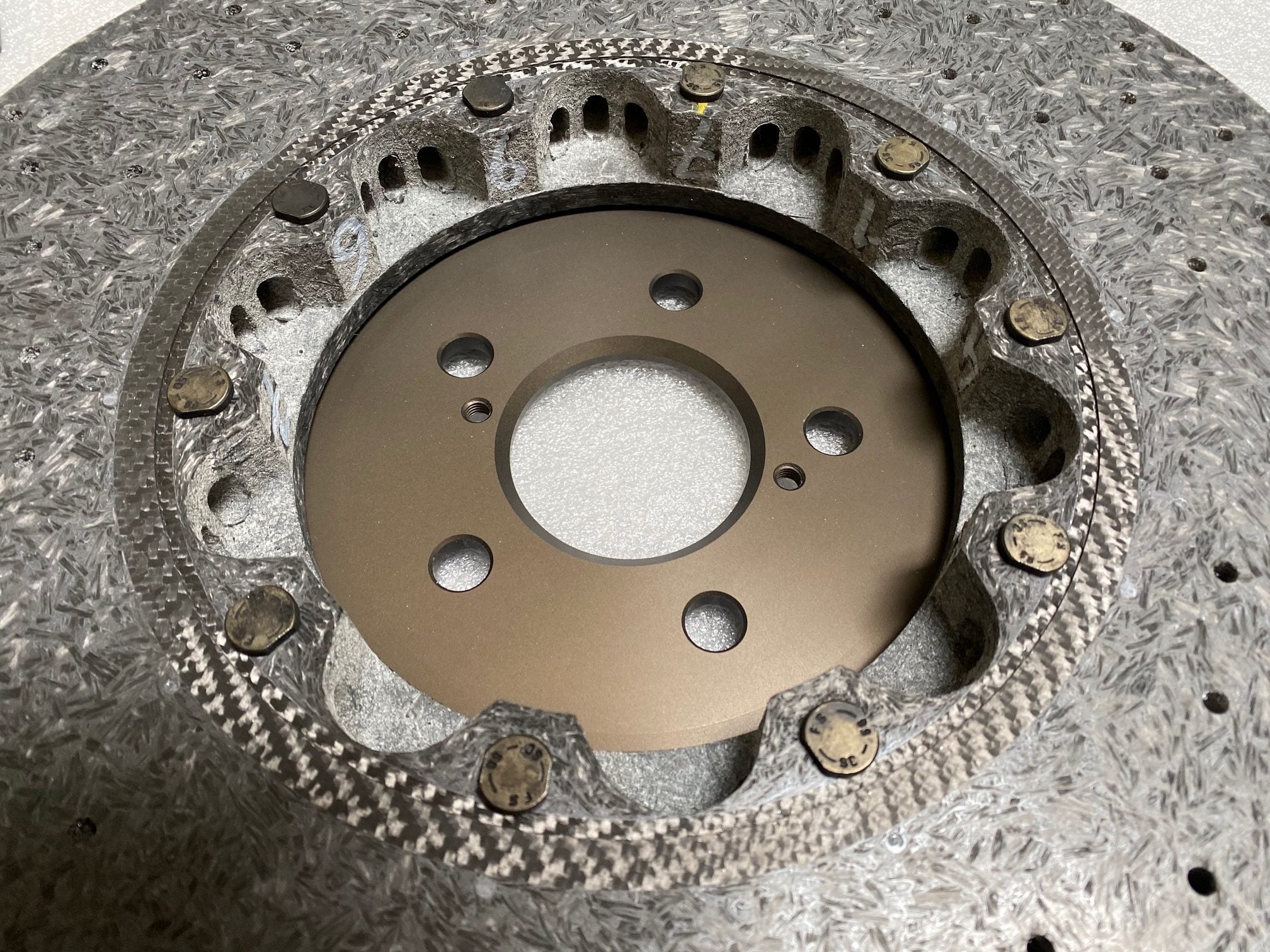
which seem to exhibit similar characteristics.
So maybe we can find out how this has been developed? The underlying patent for this type of brake construction appears to be:
https://patentimages.storage.googleapis.com/b7/c7/...
But that provides no information about the spec of the fastenings. They're just fastenings.
We know (my other post) that the "F S" marked fasteners are produced by Stabio. A bit more Google fu throws up a patent from Kunshan Yi Ke Hardwear Pty Ltd and assigned to Stabio fasteners (Kunshan) Co.,Ltd. (both in China)
https://patents.google.com/patent/CN206738353U/en
which describes a method for making a flat-headed screw in two parts. Whilst not directly comparable to the evidence provided here, it at least indicates that Stabio's asian offshoot is knowledgeable about making multi-part screw fastenings.
I may, of course, be over-thinking this. But the photo the OP provided, coupled with others (such as this from a McLaren Brembo CCM bolt):
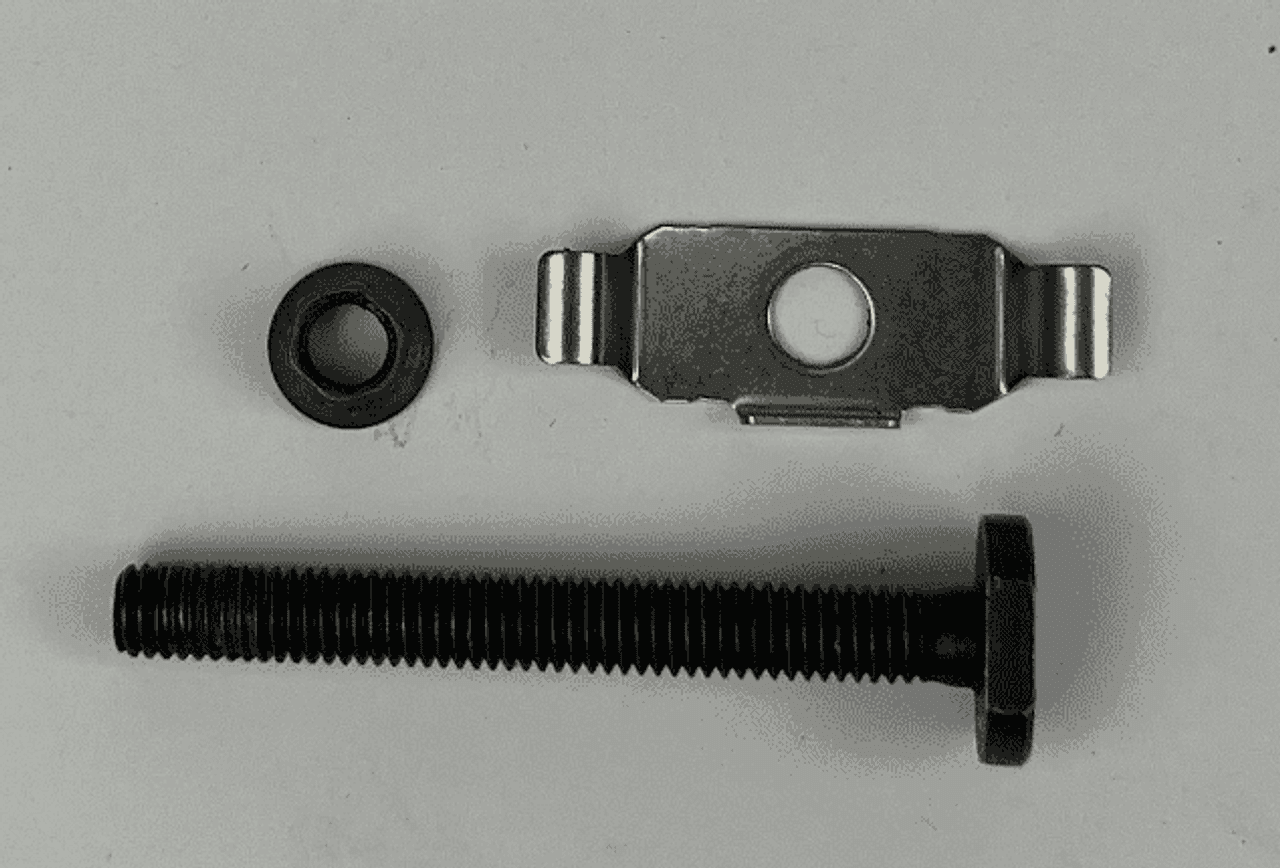
make it look a lot like this may indeed be a 2-piece screw fastener. It might be a pressed-together construction (Stabio are known for cold-forming of fastenings, never mind the patent). It might be there are known issues with re-tightening. It may be they're deliberately designed to fail under a certain load (to prevent problems in-service and/or during installation, as abo0ve). If they are welded in some way, it may be (as above) they're designed to fail in some other way.
Failures in service at the head-shank interface of single-piece screws are not unknown, of course. If these are cold-formed single pieces, it looks like there's been an awful lot of cold-forging operations to get such a flattened head. It is important for proper strength that the metal grain flow lines form in the right way, like this (good on the left, bad on the right):

Meanwhile, hydrogen embrittlement is not unknown in bolts, and can often manifest as cracks like these:

When tension is applied to the fastener, the hydrogen tends to migrate to points of high stress concentration (under the head of the fastener, first engaged thread, etc.). The pressure created by the hydrogen creates and/or extends a preexisting crack which grows under subsequent stress cycles until the bolt breaks.
And so it might be corrosion after all, perhaps preferentially attacking the area of the shank-head interface due to (deliberate or not) material grain in that region.
It would be interesting to see a new one. It would be even more interesting to cut into a new one! But it also seems at least arguable there's something rather odd about these bolts, and that re-using them would be something I'd be very cautious about until I knew rather more about them.
The lack of markings on yours also makes me wonder whether the spec has been changed along the way?
Anyhow, interesting though this rabbit hole was, I've probably fully jumped the shark on a simple bolt problem But if there are no more takeaways from this, it is worth noting that the design of bolted joints is nothing if not a full-on engineering problem at times!
Unbelievably (given the length of this post about a simple bolt), I'm skipping over some things, and simplifying others. I'm sure true bolted joint experts will be able to jump in and pick me up on them. Forgive me those; it is a long time since I designed a bolted joint in detail, and I'm trying (and probably failing) to make this at least mostly accessible to a nerdy generalist audience!
MK1RS Bruce said:
BOR said:
Julian Thompson said:
Mucho interesting. I am working on adding some S8 CCB’s to my old D3 Audi, and I’ve come up against Audi documentation that forbids touching those bolts that hold the rotor to the centre hub. Intrigued and armed with a knackered old disc I stripped the hub off and inspected it all.
Other than a specific arrangement of conical washers I can find absolutely no reason for the warning. Everything centres up automatically on assembly. No idea why they’re so insistent about it.
Here is what I'm guessing and this applies to all BMW/AUDI/Ferrari/Porsche who use this design of Brembro disc.Other than a specific arrangement of conical washers I can find absolutely no reason for the warning. Everything centres up automatically on assembly. No idea why they’re so insistent about it.
These are probably stretch bolts that are being tightened using torque+angle to put the bolt into plastic deformation.
This is done to maintain the clamping load on the disc as the bolt shortens and lengthens as the temperature hits it.
You can imagine the ceramic has a really low coefficient of thermal expansion and the bolt, despite the added titanium, will expand a lot more. In an extreme case, the bolt could expand so much, that there is no longer any clamping force on the disc.
Putting the bolt into plastic deformation should mean that the clamping force changes much less as the temperature changes, as the force now moves back and forth on the flat part of the curve.
You won't be able to do this with your Halfords torque wrench.
My first thoughts were that these bolts should be treated as consumables and regularly replaced, but I now think it is not quite so simple as I initially thought.
Of course, I could have this completely back-to-front.
pre-loading the fasteners to a set torque is to protect them from fatigue loading normally??
Most joints change. Gaskets shrink. Components expand and contract with heat (including bolts themselves). Every component adds weight and cost.
In designing a bolted joint, the questions are broadly:
(a) how do I get the maximum clamping force from the minimum-sized component; and
(b) how do I get the minimum change in clamping force from my fastening with any change in the geometry of my joint; and
(c) how do I minimise fatigue issues; and
(d) how do I get the most consistently-installed clamping force?
(a) is easy - if the bolt is at (or very close to) yield, that's the maximum clamping force you can get from that bolt (well, almost - see below). So a torque-to-yield fastener is going to give us the maximum force for that size of fastener.
(b) is geometrical. Let's consider two bolts, of diameter 6mm and 8mm. We want a clamping force equivalent to a load in the bolt of 8kN.
At 8kN, our two bolts both stretch. Let's say (numbers made up for illustration) that at 8kN load, we find:
- our 6mm bolt stretches 1.8mm
- our 8mm bolt stretches 0.8mm
Let's assume (to make the illustration easier to visualise) we have a gasket in our joint. Let's say it was 1.2mm when installed, and that it relaxes under load by 25% - a net loss of 0.3mm.
Either bolt will pull the joint closed. But in the elastic region, a reduction in strain (stretch) will be proportional to a reduction in load in the bolt. So:
- our 6mm bolt loses 0.3/1.8 of the load, leaving 6.7kN
- our 8mm bolt loses 0.3/0.8 of the load, leaving 5kN
Therefore using an 8mm bolt in place of a 6mm bolt gives us a variation in clamping force (in response to gasket relaxation) of 38%, vs only 16% for the 6mm bolt.
So that's why we want the smallest bolt possible, which means it has to be tightened to at - or very close to - yield.
(c) is all to do with S-N curves - where "S" is the stress range (i.e. max-to-min load) and "N" is the number of cycles to fatigue failure. Higher "S" gives lower "N" to fatigue failure (very broadly). Since our torque-to-yield fastener has (by the calculations above) the smallest possible change in load with joint geometry changes, so "S" is minimised, to the benefit of "N."
Obviously it is more complex than that - there's also a stress endurance limit, which is the stress range below which no damage occurs in the face of cyclical load, but we're going to assume for a thin-as-possible bolt we don't get to choose to be below the endurance limit. If we wanted to ensure no fatigue were possible then we'd go with either a different joint design, or a much fatter joint and handle the load-changes differently.
Engineering is usually about compromises
(d) is about making sure we can predict the clamping force after installation. Assuming we're going to "torque" the joint with a socket / spanner (and not with some sort of hydraulic tensioning rig), we have to relate what we can measure at-the-spanner to the load in the bolt.
In the old days, we used to just apply a measured torque. The problem is that torque ("torque it up to XX Nm") isn't just clamping: it is also overcoming friction (under the bolt head, in the threads, etc.). If you lubricate a bolt before torquing, the clamping force can be way, way higher than if you don't, for instance. In extremis, you can torque up a well-oiled bolt "to spec" and have it snap before it get to the spec torque.
That's not good, because it doesn't allow proper - predictable - control of the clamping force. And it is - usually - the clamping force we're worried about.
There's another way to do that - "torque angle" - where you do up the bolt a bit (say 5 Nm, just enough to know you're now building load in the bolt, i.e. the joint is "done up" at a basic level), and then tighten by *angles*. Because the thread pitch is known, as are the other dimensions, a known angular deflection will give rise to a known strain (stretch) and therefore a known clamping force - because, assuming the material of the bolt is still in the elastic region, stress and strain will be perfectly correlated in a predictable fashion.
But even a "torque angle" approach doesn't guarantee the clamping force; it just attempts to control for one variable. It is still very hard to get things to the point of a consistent fastener load.
What would be great is if we could torque it up to yield, and do so reliably. That's made much easier by the shape of the stress-strain curve. The yield point isn't the start of the flat-topped curve everyone imagines. There is plastic deformation, but (to start with) the bolt can still carry more load. It is just that the stress-strain curve has flattened out. Strain hardening means the bolt can continue to carry more load (for a while), but the deformation is permanent. This is why torque-to-yield is so handy - you can get to the yield point, and go a little bit further, and the load will level off - you get a much more accurate bolt pre-load, whilst also reducing the clamp load variability (as above).
Here's a simplified diagram somebody else drew:
So our tightening becomes much easier - we just need to get past yield, and not far enough to go "over the hump." As you can see from the flattening, it just a much bigger area to aim for when measuring in "how many degrees of rotation to yield."
OK, so all of that's fine. But surely, if the bolt is tightened to yield, how can it carry increased loads (thermal stress, cyclic stresses, etc.) without just plastically deforming?
First, there's post-torquing settlement of the joint. The materials in the fastener and interface stacks will never be perfectly smooth, perfectly aligned, and so on. The threads will be imperfect, and there's a fair degree of friction (in a conventionally-torqued bolt, as much as 1/3 of the applied torque results in torsional stress in the bolt, not axial load) - but with a bit of time, that torsional stress will relax a touch. In the old days, it was said one should torque up a bolt, leave it for a while, hit the whole assembly with a large hammer, and then re-torque it
So in the real world, there will often be a slight reduction in bolt tension after tightening. That provides a (very small) portion of elastic region remaining to accommodate any slight stress increases. That's almost always sufficient. Remember, once we've reached yield, the stress-strain curve for removal of load isn't a reverse down the yield slope; it is an elastic relaxation (steep curve) from the end of tightening. So the joint settlement will leave us with a very small elastic window of operation.
In many gasketed joints, the effect is much more pronounced, as per the calculation above. The bolt relaxes down the elastic stress-strain curve quite a bit, but we're still left with a predictably-consistent clamping load across multiple bolts (important in our CCM brake disc).
That's one of the reasons you should never re-use compressible gaskets if you can avoid it, BTW.
Obviously in these CCM discs, it is the nut that is torqued, not the bolt / machine screw, and the under-head friction is likely to be pretty low (between the "wafer" head and the CCM material), but the principle still applies even if on a smaller scale.
Second, thermal expansion is a non-issue. The bolt is very unlikely to have a lower coefficient of thermal expansion than the surrounding materials. And if it does? You'd design a different joint
So as temperature rises, the joint is likely to unload, not load up. And using a minimum-size torque-to-yield bolt ensures the minimum variation in clamping force / fastener load when that happens (as above). In any case, coefficient of thermal expansion will be known for all materials in the joint stack, so you take this into account when designing.Obviously if you start using an oxy torch to rapidly heat up the surrounding material in preference to the bolt then you might have a problem; but if that is your design load-case, you're probably not going to use this type of joint!!
However, it is also important to consider thermal contraction - if a fastening's expansion coefficient is indeed greater than the surrounding materials, any significant drop in temperature could cause an increase in axial stress. So it is important to try to ensure there's sufficient post-relaxation elastic headroom to accommodate any likely temperature drops if the relative coefficients are markedly different.
Engineering = compromises again.
Third, your joint shouldn't be designed so that external loads on the assembly lead to increased loads on the bolts. That's what the bolt pre-load is for - to create a clamping force acting in opposition to your system loads. If the internal loads in (say) your big end bearing lead to an increase in bolt load, you've got a really major problem with your design!!
In our CCM disc, the primary loads are lateral - we're stopping things from moving relative to each other in shear (i.e. a plane normal to the axis of rotational symmetry of the bolt). The clamping force is key to achieving that. Assuming everything's correctly designed by Brembo, there's no load case on the assembly that would lead to a marked increase in bolt load. If the bolt is seeing, say, shear or bending loads, then either (a) the designer needs firing, or (b) the bolt hasn't been tightened up enough, or (c) the disc material is failing under the bolt head and you've got way bigger problems!!
Now, going back to the OP's problem, the bolt loads don't seem very high to the OP. So how can they be stretch bolts? The OP said:
Fonzey said:
Even when rebuilding the disc, another one of my fixings started to snap as Michael was applying the barely noticeable 10nm of torque as per spec - so that was yet another to go in the bin.
10 Nm isn't necessarily "barely noticeable" in this context.For a regular bolted joint, with a steel bolt and friction coefficient of about 0.14, around 11 Nm torque will (all things being equal) translate into a bolt pre-load around 85% of "proof load." Proof load is typically a very high percentage of yield load. The lower the friction coefficient (including whether or not parts are lubricated), the lower the torque to achieve the given bolt load.
Let's say the friction is actually just 0.1 in this case; that would knock the proof load torque down to perhaps just 9 Nm. With a very rough torque-is-proportional-to-bolt-load relationship, getting from proof load to yield at this same friction coefficient of 0.1 would give us a torque of somewhere around.... 10 Nm
So 10 Nm may be - remarkably, given "barely noticeable" - actually in the ballpark of maximum torque.
That said, if the book spec is 10 Nm (and not a torque-angle) then I'd be surprised if these were actually stretch bolts. But perhaps they're engineered-to-yield bolts?
I would imagine (but do not now) that the CCM material might not be happy being over-loaded by the bolt head, so ensuring (as much as possible) the bolt can't be over-tightened (and, indeed, no possible running loads or abnormal loads could over-stress the CCM material) might be a part of the design brief. I'm afraid I have no experience with CCM rotor materials, however, to comment further.
Now looking at the OP's failed bolt:
I'm having a hard time believing that's all corrosion damage. There seem to be definite features there.
So I'm wondering if these bolts are in fact two-piece components, joined using - say - friction welding, deliberately hollow, and using the annular section under the head as a designed-to-yield feature?
Take a look at this photo of a 612 Scaglietti CCM disc:
If you zoom in, you can see clear annular features on the bolt heads. How did those arise?
Here's another (showing the same manufacturer text markings as the OP mentioned):
which seem to exhibit similar characteristics.
So maybe we can find out how this has been developed? The underlying patent for this type of brake construction appears to be:
https://patentimages.storage.googleapis.com/b7/c7/...
But that provides no information about the spec of the fastenings. They're just fastenings.
We know (my other post) that the "F S" marked fasteners are produced by Stabio. A bit more Google fu throws up a patent from Kunshan Yi Ke Hardwear Pty Ltd and assigned to Stabio fasteners (Kunshan) Co.,Ltd. (both in China)
https://patents.google.com/patent/CN206738353U/en
which describes a method for making a flat-headed screw in two parts. Whilst not directly comparable to the evidence provided here, it at least indicates that Stabio's asian offshoot is knowledgeable about making multi-part screw fastenings.
I may, of course, be over-thinking this. But the photo the OP provided, coupled with others (such as this from a McLaren Brembo CCM bolt):
make it look a lot like this may indeed be a 2-piece screw fastener. It might be a pressed-together construction (Stabio are known for cold-forming of fastenings, never mind the patent). It might be there are known issues with re-tightening. It may be they're deliberately designed to fail under a certain load (to prevent problems in-service and/or during installation, as abo0ve). If they are welded in some way, it may be (as above) they're designed to fail in some other way.
Failures in service at the head-shank interface of single-piece screws are not unknown, of course. If these are cold-formed single pieces, it looks like there's been an awful lot of cold-forging operations to get such a flattened head. It is important for proper strength that the metal grain flow lines form in the right way, like this (good on the left, bad on the right):
Meanwhile, hydrogen embrittlement is not unknown in bolts, and can often manifest as cracks like these:
When tension is applied to the fastener, the hydrogen tends to migrate to points of high stress concentration (under the head of the fastener, first engaged thread, etc.). The pressure created by the hydrogen creates and/or extends a preexisting crack which grows under subsequent stress cycles until the bolt breaks.
And so it might be corrosion after all, perhaps preferentially attacking the area of the shank-head interface due to (deliberate or not) material grain in that region.
It would be interesting to see a new one. It would be even more interesting to cut into a new one!
But it also seems at least arguable there's something rather odd about these bolts, and that re-using them would be something I'd be very cautious about until I knew rather more about them.The lack of markings on yours also makes me wonder whether the spec has been changed along the way?
Anyhow, interesting though this rabbit hole was, I've probably fully jumped the shark on a simple bolt problem
But if there are no more takeaways from this, it is worth noting that the design of bolted joints is nothing if not a full-on engineering problem at times!skwdenyer said:
More Bolt stuff
Incredible, fascinating stuff (no really, I mean it  ) and makes me think back to every single bolt that I've reused over the years wondering how I haven't died a horrible death a thousand times over
I've had a few more chats about these today. Found one specialist who has their own "uprated" replacement, made from inconel apparently and reeeeeeeeeeeeally expensive, but it's good to know there's an option I suppose?
I'll see if Rebrake will share any more details on the fixings they can provide. For instance if they're made by the original manufacturer of the Brembo ones, or if it's their own take on the design. If it's the former then I may find comfort in the fact they're exactly as-original, but if it's the latter then I may still pursue getting my own made up and rely on the (hopefully) good bolt making practise of whoever I find to make them.
I'm still trying to convince myself that although this bolt chat is all very useful and informative, that we're probably overthinking it and that re-using the old stuff will be 'fine'.

Fonzey said:
skwdenyer said:
More Bolt stuff
Incredible, fascinating stuff (no really, I mean it ) and makes me think back to every single bolt that I've reused over the years wondering how I haven't died a horrible death a thousand times over I've had a few more chats about these today. Found one specialist who has their own "uprated" replacement, made from inconel apparently and reeeeeeeeeeeeally expensive, but it's good to know there's an option I suppose?
I'll see if Rebrake will share any more details on the fixings they can provide. For instance if they're made by the original manufacturer of the Brembo ones, or if it's their own take on the design. If it's the former then I may find comfort in the fact they're exactly as-original, but if it's the latter then I may still pursue getting my own made up and rely on the (hopefully) good bolt making practise of whoever I find to make them.
I'm still trying to convince myself that although this bolt chat is all very useful and informative, that we're probably overthinking it and that re-using the old stuff will be 'fine'.
So most bolts can be re-used.But when a mfr says "don't re-use this bolt" it may not (especially on modern-ish cars) because they're trying to sell you spares. That's the point - if a bolt is designed not to be re-used, it really is designed not to be re-used!
And that's my slight concern here - the "new" ones you've been given are re-used, presumably, from other vehicles?
If you do replace any of your "good" ones, I'd be fascinated to see a section cut through one of them lengthways to see if they are a single piece or not. We obviously know what a heavily-corroded one looks like
skwdenyer said:
Most bolts aren't designed to the limit of clamping, etc. - because, as my post might suggest, there's an awful lot of work in doing that design! Better to use a bigger bolt, a decent lock washer and a healthy dab of Loctite So most bolts can be re-used.
But when a mfr says "don't re-use this bolt" it may not (especially on modern-ish cars) because they're trying to sell you spares. That's the point - if a bolt is designed not to be re-used, it really is designed not to be re-used!
And that's my slight concern here - the "new" ones you've been given are re-used, presumably, from other vehicles?
If you do replace any of your "good" ones, I'd be fascinated to see a section cut through one of them lengthways to see if they are a single piece or not. We obviously know what a heavily-corroded one looks like
Yep the donated ones were used, but showed zero corrosion compared to mine. So most bolts can be re-used.But when a mfr says "don't re-use this bolt" it may not (especially on modern-ish cars) because they're trying to sell you spares. That's the point - if a bolt is designed not to be re-used, it really is designed not to be re-used!
And that's my slight concern here - the "new" ones you've been given are re-used, presumably, from other vehicles?
If you do replace any of your "good" ones, I'd be fascinated to see a section cut through one of them lengthways to see if they are a single piece or not. We obviously know what a heavily-corroded one looks like
If/when I source some replacements, as reward for your incredible efforts here I'll send you one of the originals for you to chop up in as many ways as you like!
Fonzey said:
Broke Rule #1 of project thread authoring yesterday. Wall of text with no pics.
So this morning have some pics with no text. Drive needs weeding, job for today I promise.


LOVE blue over tan (my RS6 is a similar colour but with white seats - so not quite nailed it). Useable Ferrari's like the FF, 612 and 456 are all aspirational dream cars for me much more than the racier models. So this morning have some pics with no text. Drive needs weeding, job for today I promise.
Really enjoying the detail you've provided, keep the updates coming!
RS6Wheels said:
LOVE blue over tan (my RS6 is a similar colour but with white seats - so not quite nailed it). Useable Ferrari's like the FF, 612 and 456 are all aspirational dream cars for me much more than the racier models.
Really enjoying the detail you've provided, keep the updates coming!
Yeah I'm so happy with the colour combo. Makes me grin a bit every time I walk past it! I think long term I can't consider my "Ferrari box" ticked until I've owned a V8 Mid/Rear car, but it's so hard for me to justify something like that alongside the Lotus - as I fear I'd always be reaching for the Lotus key for a trackday, and going for road/weekend blasts without the family close by is becoming increasingly difficult.Really enjoying the detail you've provided, keep the updates coming!
The FF is bloody ideal though, we can go off for a nice B&B getaway or whatever and I'll always have the option to get up at the crack of dawn and go... "buy milk". Even just using it for mundane duties is a barrel of fun, I'm starting to really gel with the steering on the car now after first being taken aback at how light and fast the rack is, I'm now appreciating its accuracy. It's a properly quick car for most road conditions, but still very satisfying to drive 'normally'.
No real updates for this week yet. Been "piling the miles on", probably done 150 miles in it since getting the tyres back and loving every one of them.
Even took it to work int' City today.

At some point I need to get it booked in for a service. Need to study the terms of the Power15 warranty a bit, I know I need to take it to a main dealer at some point for a pre-warranty inspection if I do plan to extend it beyond November (I probably will), but I'm not sure if I need to have it serviced at a main dealer too. If not, I'll happily take it to the Indy that helped me with the brake bolts - but more research needed before I commit.
Next week it's going to my detailer. Unfortunately not for the full paint correction we originally planned, as it's going to go back to the bodyshop in the near future to correct a couple of snags first. They're being great to work with, and it's mutually convenient for me to keep the car for now, enjoy the good weather when we get it and then get it back to them later in the year for them to address a few more bits.
To give the detailer something to do in the meantime, he'll be ceramic coating the freshly done wheels and will give my interior a properly good sort out including treating all of the leather. Looking forward to that, as it's getting a bit dusty in there and there's a bit of shiny leather on the wheel which I reckon he can drastically improve.
Fettled a couple of jobs in the last week or so.
I mentioned in the OP that the interior had worn the age/miles very well, and I stand by that - but I have found a couple of bits of evidence of the sun-exposed leather shrinking back a bit. Luckily the lower down areas in the tan are all well sheltered and absolutely perfect.
One bit was the binnacle shroud:

You can see the leather has come unstuck underneath as it as shrunk back.
Shroud came off without any tools:

and a bit of superglue and tape allowed me to stick it back down. Ideally it needs recovering, I'm not sure if leather can be taken off, conditioned and restretched(?) but there are two bits of the dash which would benefit from such treatment if it's possible so it might be a job for winter to get it all out and looked at.

Second thing to address was some wind noise from the passenger window. The glass is all double glazed in this car and it's eerily silent inside when driving, all with the exception of the odd bark from the V12 to remind you it's still there.
When driving into wind though, or above certain speeds I got the rush of wind as if the passenger window was cracked a bit. Luckily I found the issue quickly, the seal wasn't sat flush into the corner:

Was dead easy to peel it back, clean it out and then push it back in properly.

This fixed the 'window is a bit open' soundtrack, but I've swapped it with a much worse high pitched whistle at high speed now I guess the seal has deformed to the shape of the window in the 'wrong' position for so long that now it's opened up a gap somewhere else. I've yet to track that gap down, so for now I've reached into the Lotus-owners toolkit and got my stick of this out:

Not really sure what I'm trying to achieve with it yet, at worst it will treat the rubber a bit and not really help with anything. At best it might soften the rubber up a bit and assist it in reforming to the relative glass position and add a bit of sealing properties to the interface. Failing that, I have the workshop manual and there are window adjustment steps in there to try.
Aside from that:
Missus took me to the pub:

Took photo of missus at the pub:

I took missus to another pub:

Took daughter to a playground:

Gave it a wash:

...and spent a small fortune at Shell as a result.
Loving the car now, we're grabbing the keys for it for just about every journey but I'll start ramping that down a bit soon, both for financial reasons and for preserving the special occasion nature of it
I mentioned in the OP that the interior had worn the age/miles very well, and I stand by that - but I have found a couple of bits of evidence of the sun-exposed leather shrinking back a bit. Luckily the lower down areas in the tan are all well sheltered and absolutely perfect.
One bit was the binnacle shroud:
You can see the leather has come unstuck underneath as it as shrunk back.
Shroud came off without any tools:
and a bit of superglue and tape allowed me to stick it back down. Ideally it needs recovering, I'm not sure if leather can be taken off, conditioned and restretched(?) but there are two bits of the dash which would benefit from such treatment if it's possible so it might be a job for winter to get it all out and looked at.
Second thing to address was some wind noise from the passenger window. The glass is all double glazed in this car and it's eerily silent inside when driving, all with the exception of the odd bark from the V12 to remind you it's still there.
When driving into wind though, or above certain speeds I got the rush of wind as if the passenger window was cracked a bit. Luckily I found the issue quickly, the seal wasn't sat flush into the corner:
Was dead easy to peel it back, clean it out and then push it back in properly.
This fixed the 'window is a bit open' soundtrack, but I've swapped it with a much worse high pitched whistle at high speed now
I guess the seal has deformed to the shape of the window in the 'wrong' position for so long that now it's opened up a gap somewhere else. I've yet to track that gap down, so for now I've reached into the Lotus-owners toolkit and got my stick of this out:Not really sure what I'm trying to achieve with it yet, at worst it will treat the rubber a bit and not really help with anything. At best it might soften the rubber up a bit and assist it in reforming to the relative glass position and add a bit of sealing properties to the interface. Failing that, I have the workshop manual and there are window adjustment steps in there to try.
Aside from that:
Missus took me to the pub:
Took photo of missus at the pub:
I took missus to another pub:
Took daughter to a playground:
Gave it a wash:
...and spent a small fortune at Shell as a result.
Loving the car now, we're grabbing the keys for it for just about every journey but I'll start ramping that down a bit soon, both for financial reasons and for preserving the special occasion nature of it
Gassing Station | Readers' Cars | Top of Page | What's New | My Stuff