Exige S1 over-winter Refresh
Discussion


Simon, I had a hunt but couldn't find fittings to tee off at the filter. If you can point me in the right direction I'd certainly rather go that route.
As for the weight on the fuel rail, I don't think it'd be an issue (this part I've designed up is very small and light, but as you say... if I can get something that'll just screw in at the fuel filter, then I'm much more inclined to go that route!
As for the weight on the fuel rail, I don't think it'd be an issue (this part I've designed up is very small and light, but as you say... if I can get something that'll just screw in at the fuel filter, then I'm much more inclined to go that route!

Scuffers said:
Cheers Simon, I've seen those, but the fittings on the fuel filter are M14 x 1.5 flare, not -AN. I'm trying to hunt down Metric - AN adaptors that go both ways, yet to find a good supply.Well, I've exhausted the internet and there's simply no way you can plumb a fitting to make a pressure sensor take-off at the fuel filter. The Lotus fuel system is Metric flare (just like Rover). There is no pressure take-off fitting in metric and the fittings to convert to JIC or similar don't exist without re-plumbing the entire fuel system from scratch.
The only way I can see to do it is to re-make the fuel-hose-to-fuel-rail connector with a threaded fitting allowing the use of an -AN connector there. You'd then have to make a hose up to go between the fuel filter (with -AN adaptor) and the fuel rail. There's just no easy way to do it.
As for the pressure sensor being screwed into the fuel rail... the fuel rail is plastic and is secured to the throttle bodies so there is a degree of vibration isolation there, but not a lot obviously. Looks like this is the only way sadly
Esprit said:
Well, I've exhausted the internet and there's simply no way you can plumb a fitting to make a pressure sensor take-off at the fuel filter. The Lotus fuel system is Metric flare (just like Rover). There is no pressure take-off fitting in metric and the fittings to convert to JIC or similar don't exist without re-plumbing the entire fuel system from scratch.
The only way I can see to do it is to re-make the fuel-hose-to-fuel-rail connector with a threaded fitting allowing the use of an -AN connector there. You'd then have to make a hose up to go between the fuel filter (with -AN adaptor) and the fuel rail. There's just no easy way to do it.
As for the pressure sensor being screwed into the fuel rail... the fuel rail is plastic and is secured to the throttle bodies so there is a degree of vibration isolation there, but not a lot obviously. Looks like this is the only way sadly
well, I have this on mine, and it was all off the shelf stuff....The only way I can see to do it is to re-make the fuel-hose-to-fuel-rail connector with a threaded fitting allowing the use of an -AN connector there. You'd then have to make a hose up to go between the fuel filter (with -AN adaptor) and the fuel rail. There's just no easy way to do it.
As for the pressure sensor being screwed into the fuel rail... the fuel rail is plastic and is secured to the throttle bodies so there is a degree of vibration isolation there, but not a lot obviously. Looks like this is the only way sadly
Scuffers said:
well, I have this on mine, and it was all off the shelf stuff....
Got any photos? If there's any way to do it, I certainly want to, but I've searched Goodridge, Mocal, Merlin Motorsports, Demon Tweeks, Jeg's, Summit Racing ..... can't find ANYWHERE that does a metric take-off fitting. And I can't seem to find the right conversion fittings to do it off-the-shelf. Best way I can see is to machine up an adaptor to convert the end of the fuel rail to JIC, take a hose back to the sender take-off (in JIC) and then use a metric-to-JIC converter at the fuel filter.... but that still requires machining things.Just priced up making up my own metric adaptor, it's going to cost me over $200 to buy the taps to make it, so that's out as an option too. These things shouldn't be so hard....
Well I was hoping to get away without having to re-plumb the whole system.... ideally. Trying to keep it original(ish) where possible
Might have just cracked it though. Russell Performance in the states do a bunch of cool fittings. I can use a fitting similar to that speedflow one you posted on an -AN adaptor on the end of the filter (engine side). Follow that up with a 90 degree elbow and then use a -6AN to push-on male hose which should then clip to the factory flexible hose link to the engine..... if I think about it, it MIGHT just be crazy enough to work!
Might have just cracked it though. Russell Performance in the states do a bunch of cool fittings. I can use a fitting similar to that speedflow one you posted on an -AN adaptor on the end of the filter (engine side). Follow that up with a 90 degree elbow and then use a -6AN to push-on male hose which should then clip to the factory flexible hose link to the engine..... if I think about it, it MIGHT just be crazy enough to work!
fatwomble said:
TonyHetherington said:
Just to say I'm still LOVING this thread
so am I but I think it has put me off ever doing a similar exercise.Esprit, keep it up. You are an inspiration to many, even to me. I just cant do anything about it

Well it's been a lovely weekend here weather-wise. Bracing, yet sunny... which signals that winter's past the halfway point and reminds me that spring is just around the corner. Spurred on by this, I've had a busy week with the car... only a little progress but many hours have been spent.
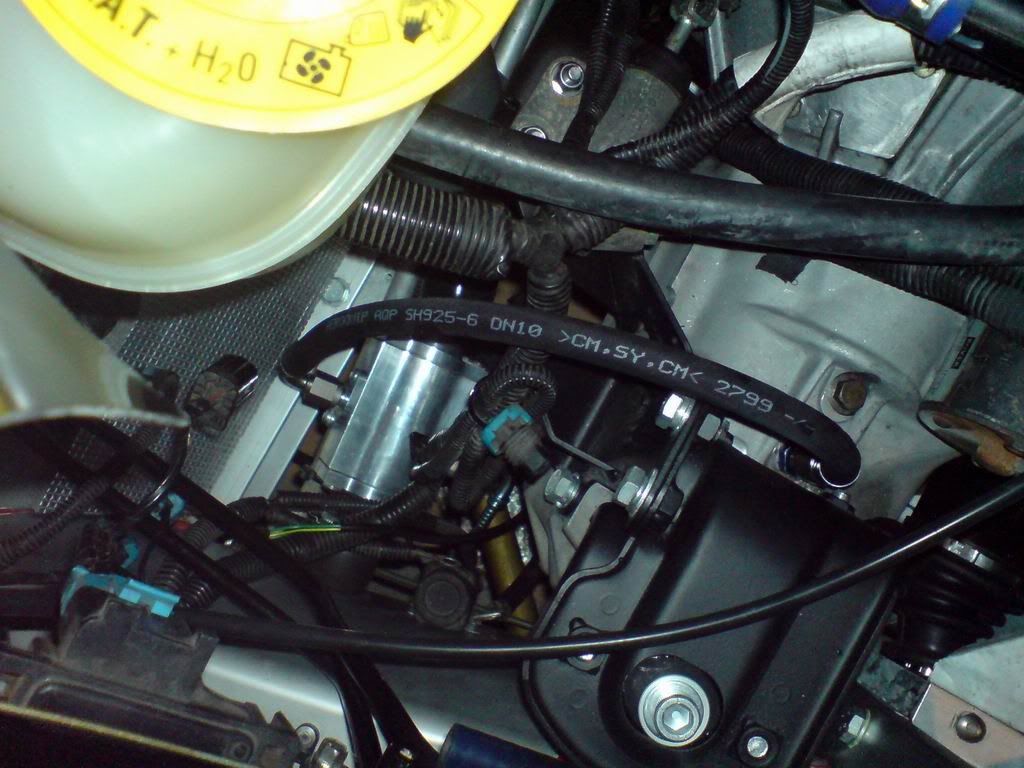
First thing I've done is junked last week's idea of mounting the fuel pressure takeoff on the fuel rail. On advice that pressure sensors don't generally like vibration, it was a safer bet to mount this sensor back on the chassis. The most logical place to do this is on the downstream side of the fuel filter (item 7 in the following image):
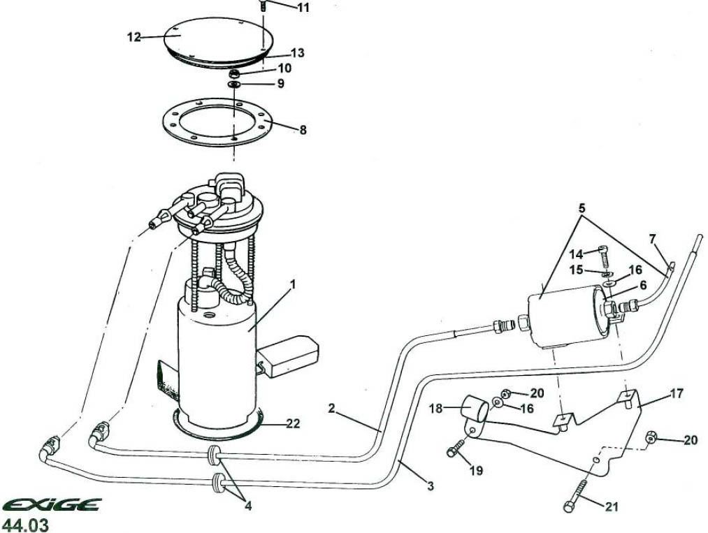
Now, this proved a little hard since the fitting involved was a M14 x 1.5 concave flare fitting, which isn't the most common. I could convert from it to -JIC/-AN easily enough, but then converting back to M14 concave flare thereafter to match up with the OEM tubing was proving a nightmare to sort out.
Thankfully, the guys at Russell fittings in the US have just the trick as they sell -AN to SAE push-fit fitting adaptors meaning that instead of inserting something between the fuel filter and item #7 in the above image, I could simply make up a piece to replace item #7 altogether.
One quick e-mail to the wonderful guys Jegs High Performance (www.jegs.com) in the states, and a few days later, I had the setup sitting on my desk at work:
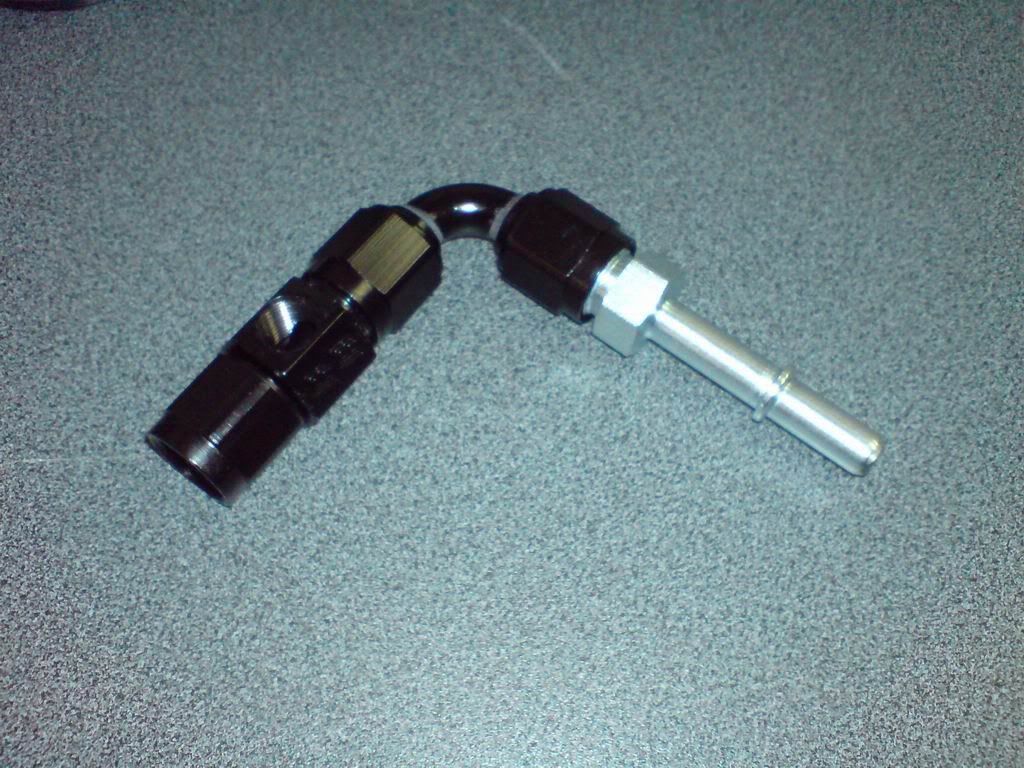
This will enable me to mount a pressure sensor (1/8" NPT) into the fuel line and datalog what the fuel pressure is doing within the Link G4.
The above setup still requires a male/male M14 x 1.5 to -6JIC adaptor, but that's coming next week along with a big bunch of fittings I'm getting from Merlin Motorsport in the UK (www.merlinmotorsport.co.uk). From here is coming my new gearbox cooler pump, fuel pressure sensor and all the hose and fittings I should need to finish most of the car off.
Much of this weekend has been spent generating this shopping list of fittings and figuring out where everything's going to go.
Also I've been doing a bit more work on the plug for the dashboard gauge pod. This is now ready for final priming and sanding and will get a topcoat and waxing prior to me taking moulds off it.
Once all my fittings and hose arrives, I'll be able to get the engine and box all sealed up. Then the wiring begins!
Oh and one other job is that I've managed to relocate the reverse light switch from the PG1 box across to the Quaife box... hopefully it works.
First thing I've done is junked last week's idea of mounting the fuel pressure takeoff on the fuel rail. On advice that pressure sensors don't generally like vibration, it was a safer bet to mount this sensor back on the chassis. The most logical place to do this is on the downstream side of the fuel filter (item 7 in the following image):
Now, this proved a little hard since the fitting involved was a M14 x 1.5 concave flare fitting, which isn't the most common. I could convert from it to -JIC/-AN easily enough, but then converting back to M14 concave flare thereafter to match up with the OEM tubing was proving a nightmare to sort out.
Thankfully, the guys at Russell fittings in the US have just the trick as they sell -AN to SAE push-fit fitting adaptors meaning that instead of inserting something between the fuel filter and item #7 in the above image, I could simply make up a piece to replace item #7 altogether.
One quick e-mail to the wonderful guys Jegs High Performance (www.jegs.com) in the states, and a few days later, I had the setup sitting on my desk at work:
This will enable me to mount a pressure sensor (1/8" NPT) into the fuel line and datalog what the fuel pressure is doing within the Link G4.
The above setup still requires a male/male M14 x 1.5 to -6JIC adaptor, but that's coming next week along with a big bunch of fittings I'm getting from Merlin Motorsport in the UK (www.merlinmotorsport.co.uk). From here is coming my new gearbox cooler pump, fuel pressure sensor and all the hose and fittings I should need to finish most of the car off.
Much of this weekend has been spent generating this shopping list of fittings and figuring out where everything's going to go.
Also I've been doing a bit more work on the plug for the dashboard gauge pod. This is now ready for final priming and sanding and will get a topcoat and waxing prior to me taking moulds off it.
Once all my fittings and hose arrives, I'll be able to get the engine and box all sealed up. Then the wiring begins!
Oh and one other job is that I've managed to relocate the reverse light switch from the PG1 box across to the Quaife box... hopefully it works.
Right, well another sunny winter's day in the garage!
I'm currently waiting for some stuff to turn up from Blighty to allow me to finish the plumbing, so today I tackled another one of those tasks I've been putting off for a while..... cleaning the underfloor!
I'd previously (about 18 months ago!) cleaned up the underfloor beneath the battery/heater compartment up front. I did this when cleaning up around the front crash structure. I've also got new engine front and rear undertrays ready to bolt on when the car's mobile again, so these parts of the underside will look shiny and new again. Today I set about cleaning up the bit in the middle as well as beneath the sills.
This was all coated with 9 years (ok, the car's only really been actually on the road for about 4) of road grime, scuffs and a little bit of spot-corrosion on the aluminium where stone / gravel impacts have gone through the anodising. This is all natural wear and tear type stuff but could easily be cleaned back to near-new condition, whereby it can be periodically cleaned and protected by application of ACF50.
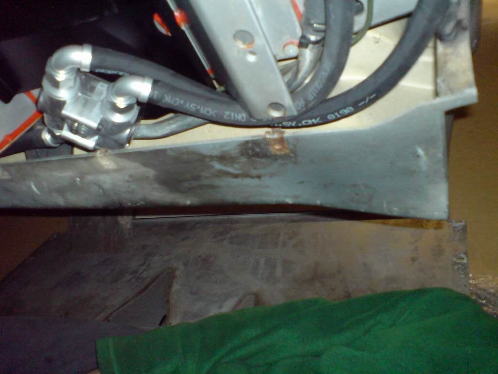
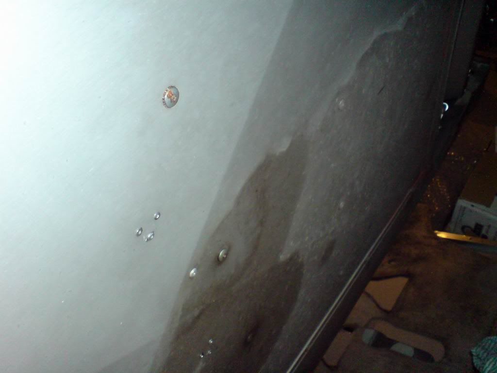
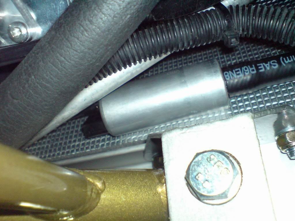
First was cleaning all the grime off the undersills. Here's a dirty one, as seen beneath the oil thermostat I recently installed:
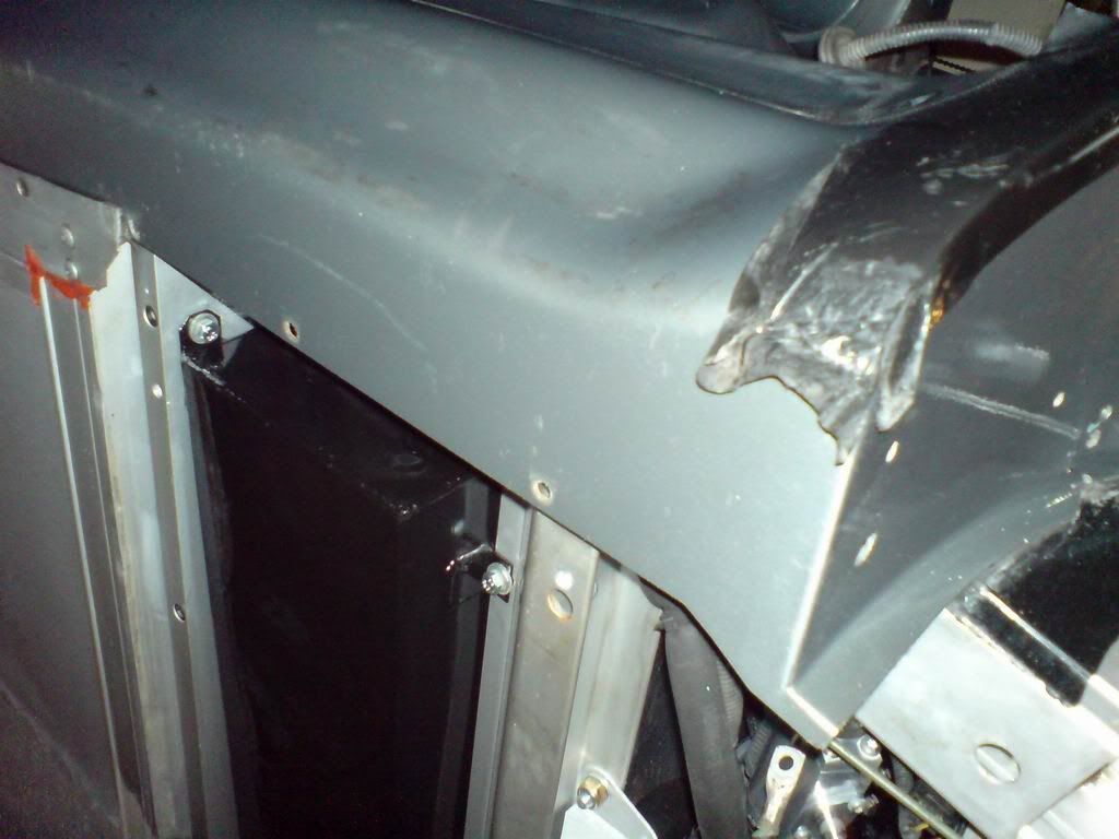
And here's a clean one I've prepared earlier.... much better:
That was the easy part, the hard part was cleaning up the large expanse of aluminium underfloor. In the end, some alkalai wash to remove as much dirt as possible, some CRC to help degrease and a large amount of Autosol to buff the accumulated crud off was used. All this required a LOT of elbow grease!
I managed to get about halfway through before I ran out of Autosol, so guess what I'm doing tomorrow after a quick trip down to Repco to get some more?!?!
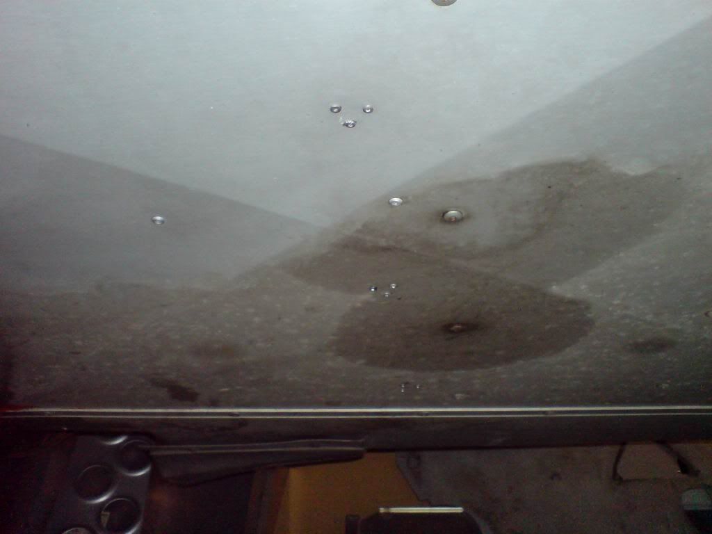
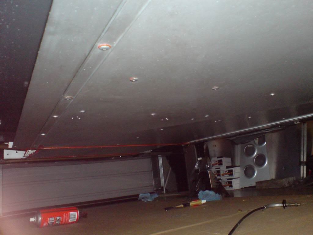
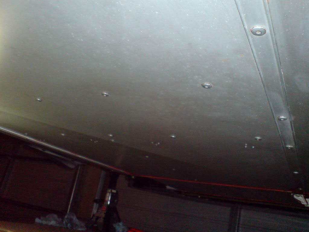
The following pics show the current state of the underfloor, with the cleaned section being closer to the camera and the still dirty section furthest away.
Mmmmm clean
I'm currently waiting for some stuff to turn up from Blighty to allow me to finish the plumbing, so today I tackled another one of those tasks I've been putting off for a while..... cleaning the underfloor!
I'd previously (about 18 months ago!) cleaned up the underfloor beneath the battery/heater compartment up front. I did this when cleaning up around the front crash structure. I've also got new engine front and rear undertrays ready to bolt on when the car's mobile again, so these parts of the underside will look shiny and new again. Today I set about cleaning up the bit in the middle as well as beneath the sills.
This was all coated with 9 years (ok, the car's only really been actually on the road for about 4) of road grime, scuffs and a little bit of spot-corrosion on the aluminium where stone / gravel impacts have gone through the anodising. This is all natural wear and tear type stuff but could easily be cleaned back to near-new condition, whereby it can be periodically cleaned and protected by application of ACF50.
First was cleaning all the grime off the undersills. Here's a dirty one, as seen beneath the oil thermostat I recently installed:
And here's a clean one I've prepared earlier.... much better:
That was the easy part, the hard part was cleaning up the large expanse of aluminium underfloor. In the end, some alkalai wash to remove as much dirt as possible, some CRC to help degrease and a large amount of Autosol to buff the accumulated crud off was used. All this required a LOT of elbow grease!
I managed to get about halfway through before I ran out of Autosol, so guess what I'm doing tomorrow after a quick trip down to Repco to get some more?!?!
The following pics show the current state of the underfloor, with the cleaned section being closer to the camera and the still dirty section furthest away.
Mmmmm clean
Frustratingly little was done over the weekend on SEXIGE because the bits I was hoping to turn up from Blighty on Friday only arrived this morning (Monday). Still, I've been out in the garage tonight tinkering and have taken a step forward.... and then a step backwards
The step backwards is in the area of the fuel pressure sender takeoff.
The picture below shows my proposed setup all mocked up next to the Lotus OEM piece:
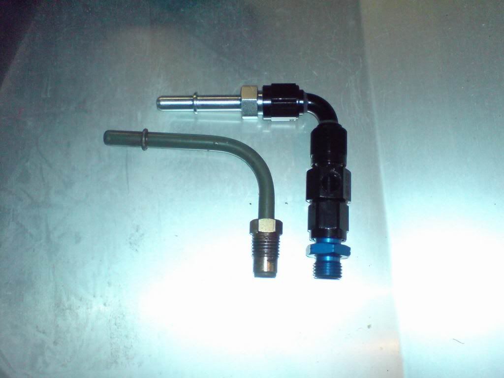
Now, you'll see from comparing the two that the M14 fitting on the end (brass fitting on the Lotus OEM bit, Anodised blue fitting on the new bit) the lengths of them are different. On the OEM fitting, the brass flare nut pulls the tapered tube flare up onto a tapered seat in the fuel filter housing. Because it's shorter on the new piece, the thread bottoms out on the hex before the tapered end of the fitting gets near the tapered seat in the filter. F**K.
Now, I could turn the hex right off the fitting altogether but I think the black hex of the next fitting in the line would almost foul too.
I'm now left either looking at achieving this differently with another fitting, making up my own custom male-to-male fitting (expensive) or modifying the fuel filter itself by sticking it in a lathe and turning the end of the filter's female boss down.
The last one is certainly the easiest for me, a ten minute job in my lunchbreak tomorrow.... but it means I'll have to modify the fuel filter every time I change it out for a new one... not quite as tidy as I'd like.
Still, I don't need to get fuel flowing through it tomorrow so there's no immediate hurry so I'll investigate it a bit further. It's just annoying because it's another thing I can't tick off the list.
I then set about working out where to position the new gearbox cooler pump. After running some test lines to test bend radii, fitting choices etc, I've settled on mounting it just above the left hand lower wishbone mount on the chassis (that's the front eye of the left hand lower rear wishbone). Seen roughly in position here:
This is a really nice position for it since it keeps the pump low (good for priming), keeps the runs short, yet allows for a good flexibility when the engine moves about on its mounts. It's also going to be reasonably easy to pick up on one of the wishbone mount-to-chassis bolts with a norma clamp or similar. I can make something up out of lasercut alloy if needs be. So much tidier and more elegant than the giant Mocal pump anyway.
Either way, very little accomplished for quite a bit of time and expense... frustrating... especially with spring just around the corner
The step backwards is in the area of the fuel pressure sender takeoff.
The picture below shows my proposed setup all mocked up next to the Lotus OEM piece:
Now, you'll see from comparing the two that the M14 fitting on the end (brass fitting on the Lotus OEM bit, Anodised blue fitting on the new bit) the lengths of them are different. On the OEM fitting, the brass flare nut pulls the tapered tube flare up onto a tapered seat in the fuel filter housing. Because it's shorter on the new piece, the thread bottoms out on the hex before the tapered end of the fitting gets near the tapered seat in the filter. F**K.
Now, I could turn the hex right off the fitting altogether but I think the black hex of the next fitting in the line would almost foul too.
I'm now left either looking at achieving this differently with another fitting, making up my own custom male-to-male fitting (expensive) or modifying the fuel filter itself by sticking it in a lathe and turning the end of the filter's female boss down.
The last one is certainly the easiest for me, a ten minute job in my lunchbreak tomorrow.... but it means I'll have to modify the fuel filter every time I change it out for a new one... not quite as tidy as I'd like.
Still, I don't need to get fuel flowing through it tomorrow so there's no immediate hurry so I'll investigate it a bit further. It's just annoying because it's another thing I can't tick off the list.
I then set about working out where to position the new gearbox cooler pump. After running some test lines to test bend radii, fitting choices etc, I've settled on mounting it just above the left hand lower wishbone mount on the chassis (that's the front eye of the left hand lower rear wishbone). Seen roughly in position here:
This is a really nice position for it since it keeps the pump low (good for priming), keeps the runs short, yet allows for a good flexibility when the engine moves about on its mounts. It's also going to be reasonably easy to pick up on one of the wishbone mount-to-chassis bolts with a norma clamp or similar. I can make something up out of lasercut alloy if needs be. So much tidier and more elegant than the giant Mocal pump anyway.
Either way, very little accomplished for quite a bit of time and expense... frustrating... especially with spring just around the corner
Scuffers said:
George,
just noticed, it's only 2 weeks short of 2 years you have been at this.....
Chop chop!
Been at it longer than that Simon... pulled the car from the road Easter '08! so we're almost up to 2.5 years. We're nearing the car's third birthday in my ownership and it only spent the first 5 months of that mobile!just noticed, it's only 2 weeks short of 2 years you have been at this.....
Chop chop!
Just trying to get this damned plumbing finished then I'll be hiring in help to do the wiring so hopefully things should progress quite quickly once all the mechanical gubbins is finished, which it nearly is
Couple of days off work at the moment struck down with a midwinter virus. With 7 guys crammed into a small office and with half of them coughing their lungs up for the last month it was only a matter of time until I got it.
Been spending most of my time resting, but today started another little job on the to-do list.... the mounting of the ECU.
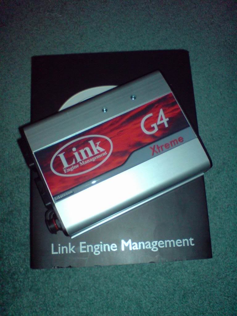
Now you may or may not recall that I'm bucking the accepted path of running the K on an Emerald and am trying the latest Link G4 Xtreme. This was chosen for its excellent capability for the money (it's one of the best ECUs I could find on the market at the moment, does most of what a high-end MoTeC does, at a quarter the price) and also since it's a NZ product there's more local support and tuning knowledge.
I've also begun to make up a loom adaptor box. This will allow me to connect the Exige Loom to the new ECU without cutting a single wire, the ECU installation will be 100% reversible. Any new wires run will be run into the adaptor box itself, and seamlessly integrated with the existing wiring. The shell and connector for this has been fabricated, but that's all at this stage:
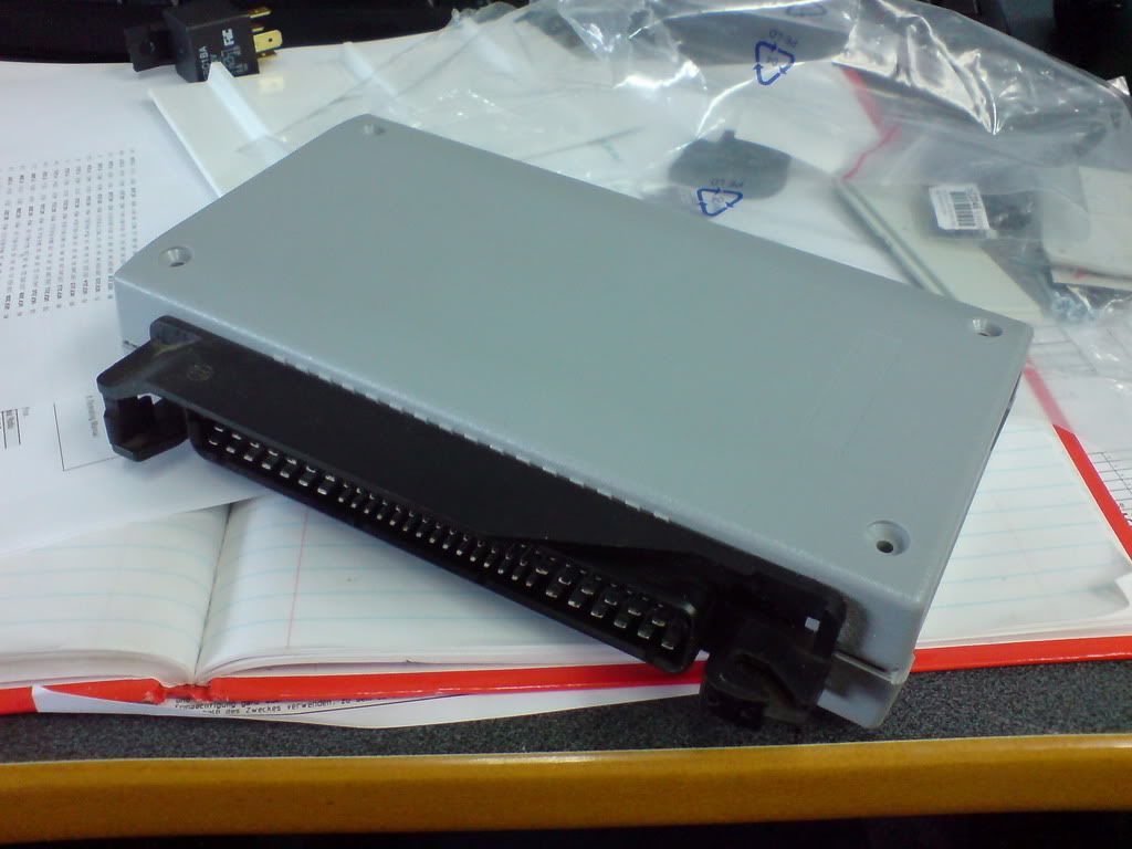
The task was now to see if I could fit this into the space taken up by the original VHPD ECU behind the passenger seat, on the bulkhead:
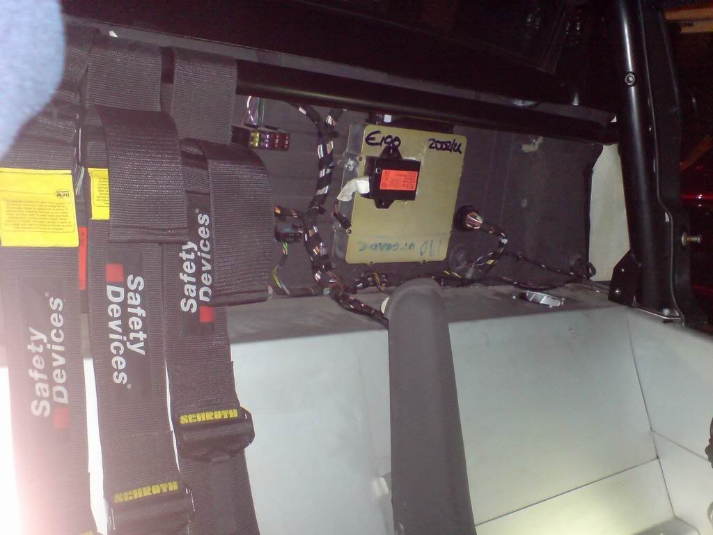

The small black box stuck to the front of the ECU is the microwave sensor for the alarm.
I modelled up the existing ECU in SolidWorks as well as the adaptor box, LINK ECU and the LINK ECU Mount. I was then able to play around with the positioning to get the loom plug in the right position. Given that there's not a lot of leeway with the large connector on the Exige loom, this really becomes the datum position for the new assembly.
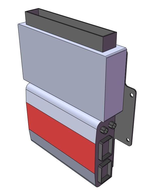
The final assembly will look something like this:
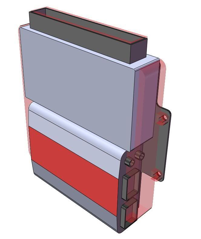
This can be seen with the silhouette of the original ECU superimposed in transparent red:
This is all mounted on a lasercut alloy bracket that'll look something like this:
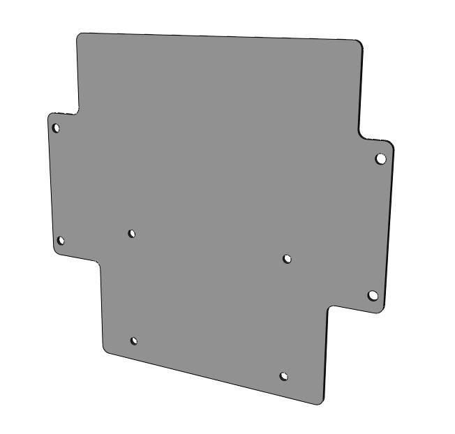
This will enable me to pick up on the original mounts for the Lotus ECU in the bulkhead, no drilling or extra fixings necessary. I've still a bit more work to do on the mount plate as I'll cut a bunch more metal out of it (add lightness!) but that's the basic shape with the necessary pick-up points.
As you can see, the new setup will sit a little deeper than the original ECU. This is no problem as there's a chunk of space there (as indicated by the fact that the alarm sensor sits atop the ECU at present. I'll probably have to stick this elsewhere but there's plenty of space for this in isolation.
The new arrangement should fit neatly and very snugly (2mm to spare!) in the gap left by the old ECU... it'll look like 'twas made to be there!
Will get this cut in the next fortnight and test-mount it in place so that it's in-situ by the time the wiring needs to begin.
Been spending most of my time resting, but today started another little job on the to-do list.... the mounting of the ECU.
Now you may or may not recall that I'm bucking the accepted path of running the K on an Emerald and am trying the latest Link G4 Xtreme. This was chosen for its excellent capability for the money (it's one of the best ECUs I could find on the market at the moment, does most of what a high-end MoTeC does, at a quarter the price) and also since it's a NZ product there's more local support and tuning knowledge.
I've also begun to make up a loom adaptor box. This will allow me to connect the Exige Loom to the new ECU without cutting a single wire, the ECU installation will be 100% reversible. Any new wires run will be run into the adaptor box itself, and seamlessly integrated with the existing wiring. The shell and connector for this has been fabricated, but that's all at this stage:
The task was now to see if I could fit this into the space taken up by the original VHPD ECU behind the passenger seat, on the bulkhead:
The small black box stuck to the front of the ECU is the microwave sensor for the alarm.
I modelled up the existing ECU in SolidWorks as well as the adaptor box, LINK ECU and the LINK ECU Mount. I was then able to play around with the positioning to get the loom plug in the right position. Given that there's not a lot of leeway with the large connector on the Exige loom, this really becomes the datum position for the new assembly.
The final assembly will look something like this:
This can be seen with the silhouette of the original ECU superimposed in transparent red:
This is all mounted on a lasercut alloy bracket that'll look something like this:
This will enable me to pick up on the original mounts for the Lotus ECU in the bulkhead, no drilling or extra fixings necessary. I've still a bit more work to do on the mount plate as I'll cut a bunch more metal out of it (add lightness!) but that's the basic shape with the necessary pick-up points.
As you can see, the new setup will sit a little deeper than the original ECU. This is no problem as there's a chunk of space there (as indicated by the fact that the alarm sensor sits atop the ECU at present. I'll probably have to stick this elsewhere but there's plenty of space for this in isolation.
The new arrangement should fit neatly and very snugly (2mm to spare!) in the gap left by the old ECU... it'll look like 'twas made to be there!
Will get this cut in the next fortnight and test-mount it in place so that it's in-situ by the time the wiring needs to begin.
Edited by Esprit on Thursday 12th August 17:03
Well this weekend's been a little disrupted, but I've still found a bit of time to get into the garage and do some more work on the car.
First little job was to source some clamps to allow me to mount the gearbox cooler pump. These have had to be ordered from Oz and will hopefully be here during next week. This is preventing me from finishing the routing on this.
The bit I CAN finish though, is the oil return line from the cooler to the gearbox. An hour in the garage making up the line today and I've got it installed. Central in the picture you can see it running from the cooler near the firewall up to the top of the gearbox. There's just enough of a loop there to allow for engine movement without the line rubbing on anything.
The other job I'm starting is thinking about air filtration.... this is a bit of a long story.
The airbox can be seen below. It's a carbon-fibre box that sits over the trumpets and bolts to the trumpet backplate. The flexible trunking then runs over to the left hand side-duct on the car.
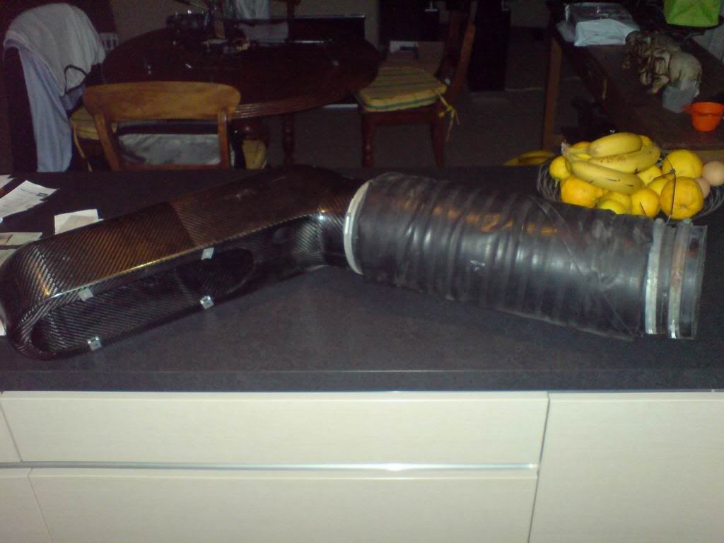
In the mouth of the trunking, is an air filter, commonly referred to as a "witch's tit", since it's a flat-conical shaped cone filter resembling a cross between a witch's hat and some prominent female chestular topography. Some Exiges have two of these (one at the trunking mouth, the other at the junction between the trunking and the airbox.... although this is more about quietening down induction noise rather than filtration. Mine had just the one.
The filter can be seen in place at the end of the trunking here:
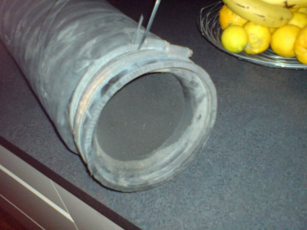
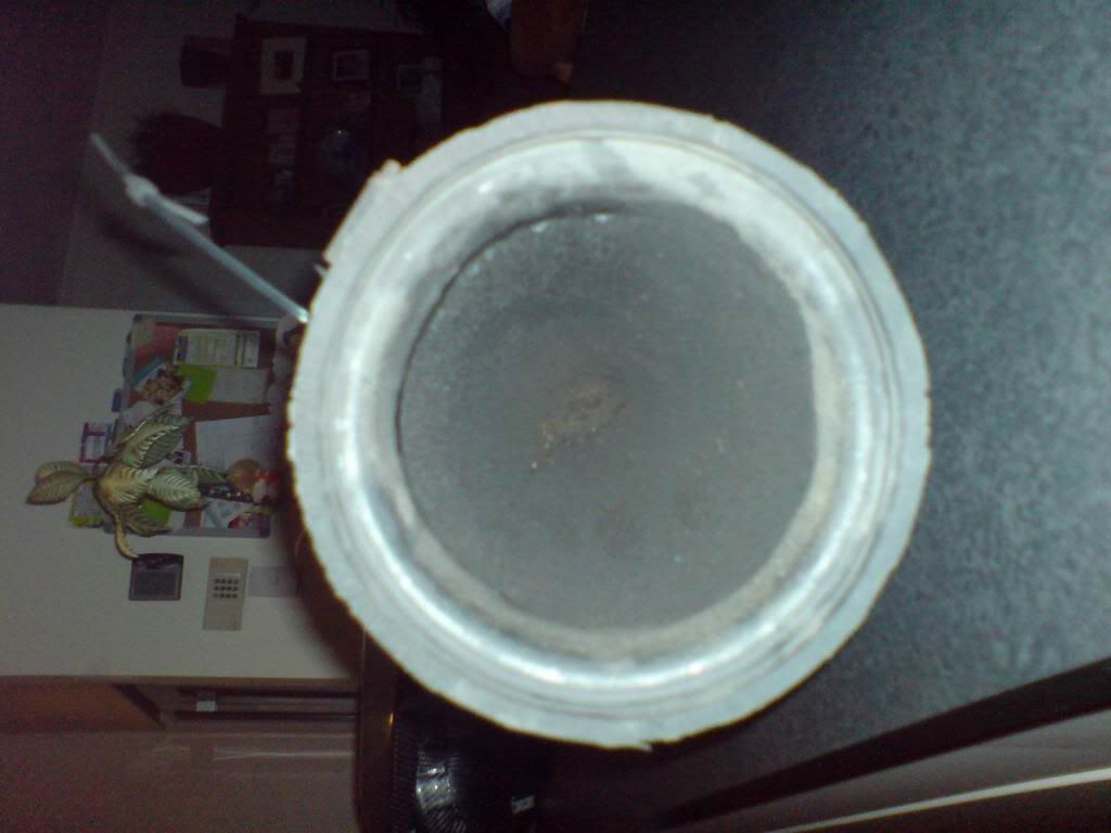
Given the small area of this filter, and its position right in the duct, it's fairly restrictive and becomes damaged / clogged easily by road debris. The general accepted solution is to run a sausage-style filter inside the airbox itself where the area is large and the air velocity is low.
ITG make Lotus specific filters, but they're very much not cheap. They come with their own filter back-plates, which clamp to the filter (sandwiching the airbox, instead of bolting to it).
Clive (Mr Bean from SELOC/Exiges.com) posted up an interesting mod he did on his ITG filter whereby he was able to adapt his ITG filter to run on the OEM backplate. He also had a spare filter I bought off him as I intended to do the same modification.
This is where things get tricky. There are two ITG Lotus kits. One is the original Lotus Sport kit (LKP100700). This was originally developed for the Lotus Sport 190 kit. Then later on, ITG also did a "LC74" version of their "Megaflow" filter which was more specifically for the Exige. I thought these two were the same, but they're not quite.
The one that Clive used and the one I got was an LKP100700, and when it arrived, I had my doubts. It's more of a wedge-shaped filter than the photos suggest, especially at the ends and I felt that the filter runs a little too close to the #1 and #4 trumpet and could disrupt the airflow somewhat.
I bit the bullet and also ordered a JC74 kit. This means I ended up with two filter assemblies, but this allows me to examine the differences. The photos below show both side by side. The LKP100700 is the slightly shallower, more tapered filter with the silver backplate and the JC74 is the more domed filter with the red backplate:
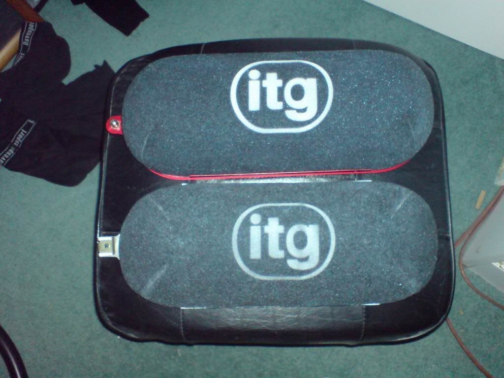
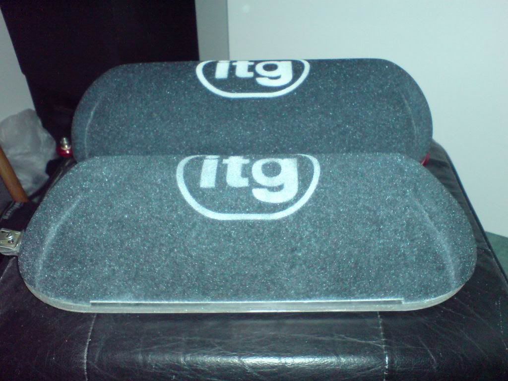
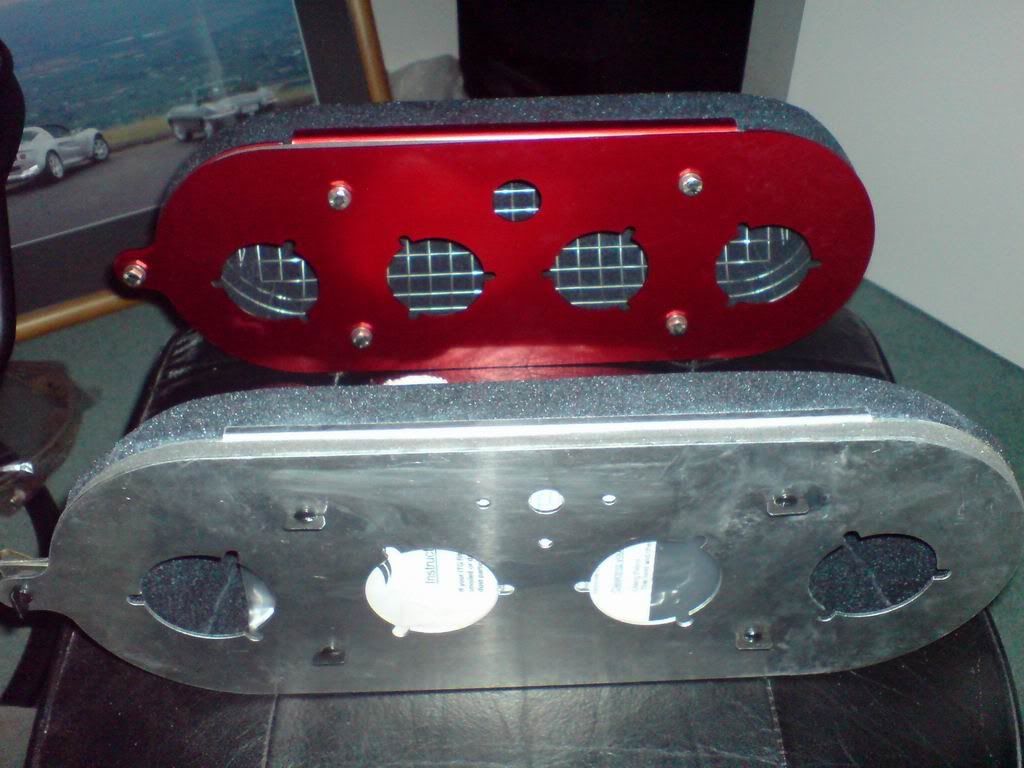
As you can see, the JC74 has a lot more clearance around the end trumpets. It also does away with the 1/4-turn dzus fasteners of the LKP in favour of M6 screws and rivnuts. This made the choice easy since the JC74-s clearly the better filter for the application of the two. The difference comes about due to the Sport 190 Elise's shallower airbox I think.
The only problem is that the construction of the JC74 means that Clive's modification to use the stock backplate won't work, which means the custom alloy backplate I made up might have to be rejected. The reason for not using the ITG-supplied backplate is that the filter fasteners supposedly end up in a really inaccessible position... which I'll have to try sometime this week with a test fitting.
Either way there's going to have to be some small modification made somewhere to make everything fit as it should... will require a little more thought, but I'm sure that I'll be able to find a workable solution.... I always do.
First little job was to source some clamps to allow me to mount the gearbox cooler pump. These have had to be ordered from Oz and will hopefully be here during next week. This is preventing me from finishing the routing on this.
The bit I CAN finish though, is the oil return line from the cooler to the gearbox. An hour in the garage making up the line today and I've got it installed. Central in the picture you can see it running from the cooler near the firewall up to the top of the gearbox. There's just enough of a loop there to allow for engine movement without the line rubbing on anything.
The other job I'm starting is thinking about air filtration.... this is a bit of a long story.
The airbox can be seen below. It's a carbon-fibre box that sits over the trumpets and bolts to the trumpet backplate. The flexible trunking then runs over to the left hand side-duct on the car.
In the mouth of the trunking, is an air filter, commonly referred to as a "witch's tit", since it's a flat-conical shaped cone filter resembling a cross between a witch's hat and some prominent female chestular topography. Some Exiges have two of these (one at the trunking mouth, the other at the junction between the trunking and the airbox.... although this is more about quietening down induction noise rather than filtration. Mine had just the one.
The filter can be seen in place at the end of the trunking here:
Given the small area of this filter, and its position right in the duct, it's fairly restrictive and becomes damaged / clogged easily by road debris. The general accepted solution is to run a sausage-style filter inside the airbox itself where the area is large and the air velocity is low.
ITG make Lotus specific filters, but they're very much not cheap. They come with their own filter back-plates, which clamp to the filter (sandwiching the airbox, instead of bolting to it).
Clive (Mr Bean from SELOC/Exiges.com) posted up an interesting mod he did on his ITG filter whereby he was able to adapt his ITG filter to run on the OEM backplate. He also had a spare filter I bought off him as I intended to do the same modification.
This is where things get tricky. There are two ITG Lotus kits. One is the original Lotus Sport kit (LKP100700). This was originally developed for the Lotus Sport 190 kit. Then later on, ITG also did a "LC74" version of their "Megaflow" filter which was more specifically for the Exige. I thought these two were the same, but they're not quite.
The one that Clive used and the one I got was an LKP100700, and when it arrived, I had my doubts. It's more of a wedge-shaped filter than the photos suggest, especially at the ends and I felt that the filter runs a little too close to the #1 and #4 trumpet and could disrupt the airflow somewhat.
I bit the bullet and also ordered a JC74 kit. This means I ended up with two filter assemblies, but this allows me to examine the differences. The photos below show both side by side. The LKP100700 is the slightly shallower, more tapered filter with the silver backplate and the JC74 is the more domed filter with the red backplate:
As you can see, the JC74 has a lot more clearance around the end trumpets. It also does away with the 1/4-turn dzus fasteners of the LKP in favour of M6 screws and rivnuts. This made the choice easy since the JC74-s clearly the better filter for the application of the two. The difference comes about due to the Sport 190 Elise's shallower airbox I think.
The only problem is that the construction of the JC74 means that Clive's modification to use the stock backplate won't work, which means the custom alloy backplate I made up might have to be rejected. The reason for not using the ITG-supplied backplate is that the filter fasteners supposedly end up in a really inaccessible position... which I'll have to try sometime this week with a test fitting.
Either way there's going to have to be some small modification made somewhere to make everything fit as it should... will require a little more thought, but I'm sure that I'll be able to find a workable solution.... I always do.
Well a very fruitful Tuesday night working on the car. Went back into work after the gym and measured a bunch of stuff up.
Turns out the Metric/DIN M14x1.5 adaptors you can buy off the shelf run a 30 degree female taper. From measuring the flare fitting on the Lotus OEM fuel filter outlet it looked very much like 45 degrees, which backs up my research.
This meant that even if the fuel fitting had been long enough the incompatible tapers would have resulted in a lousy seal.
So 15 minutes on SolidWorks and 45 minutes on the lathe downstairs and I turned myself up an adaptor:
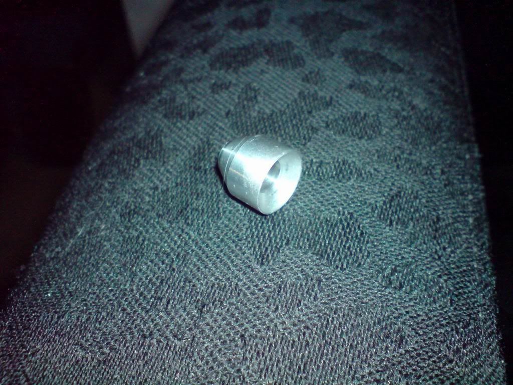
This has the right tapers on each end to mate the Goodridge fitting and the Exige fuel filter taper on the other.... it pinches up nice and tight suggesting the tapers are spot on... the proof will be when I raise fuel pressure, but for now I think we'll call that one done
Here's the fuel pressure sensor setup all fitted (apologies for the blurry pic).... Job doneski!
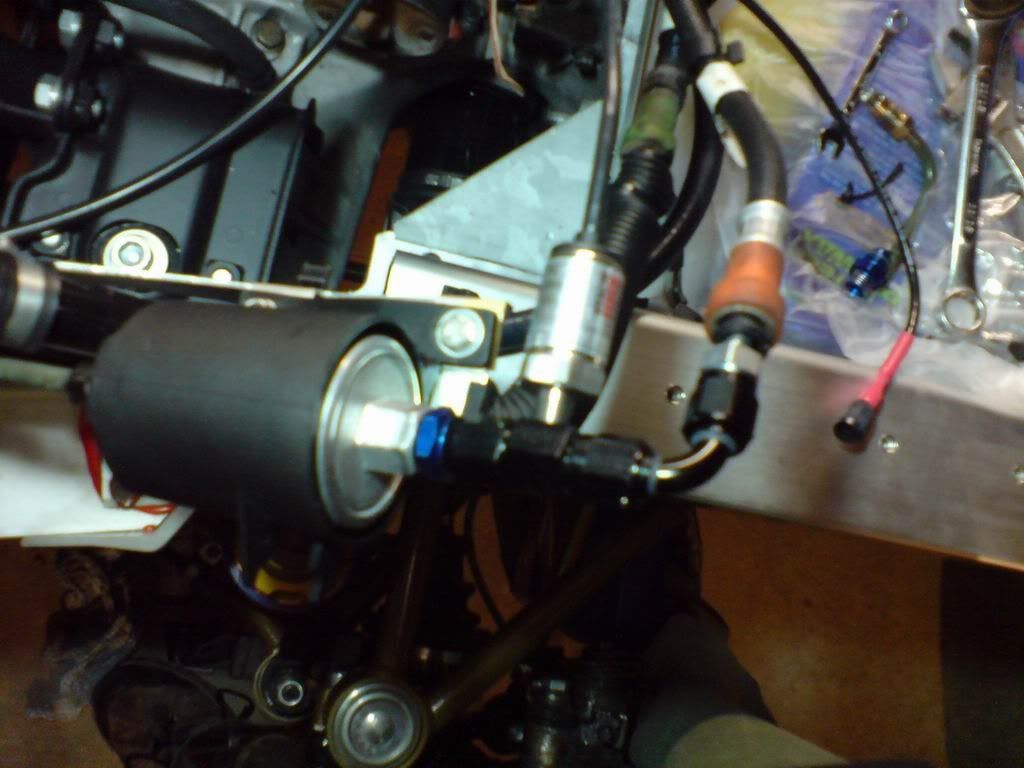
Turns out the Metric/DIN M14x1.5 adaptors you can buy off the shelf run a 30 degree female taper. From measuring the flare fitting on the Lotus OEM fuel filter outlet it looked very much like 45 degrees, which backs up my research.
This meant that even if the fuel fitting had been long enough the incompatible tapers would have resulted in a lousy seal.
So 15 minutes on SolidWorks and 45 minutes on the lathe downstairs and I turned myself up an adaptor:
This has the right tapers on each end to mate the Goodridge fitting and the Exige fuel filter taper on the other.... it pinches up nice and tight suggesting the tapers are spot on... the proof will be when I raise fuel pressure, but for now I think we'll call that one done
Here's the fuel pressure sensor setup all fitted (apologies for the blurry pic).... Job doneski!
Gassing Station | Elise/Exige/Europa/340R | Top of Page | What's New | My Stuff