Trinary switch replacement - wiring how to.
Discussion


Had to do a bit of research for this as the new switch I received had no wiring pin-out and the wrong plugs supplied.
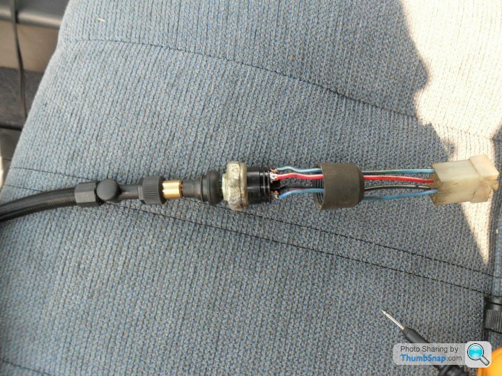
Here is the test rig
This identified the Blue/Red and Blue/White wires on the original switch as the low/high pressure switch as there was continuity at 25psi ish.
I then performed the same function test on the new switch and identified the low pressure side again (This was the black/green pair). I've assumed the matching wire colours are the 2 connections for each separate switch due to the continuity on the low side and the paired connectors (as it was received). I combined this with the original wire identification in the front body loom and have ended up with the following table.
First colour is the main wire colour, second colour is the tracer.
A few more pics from the work
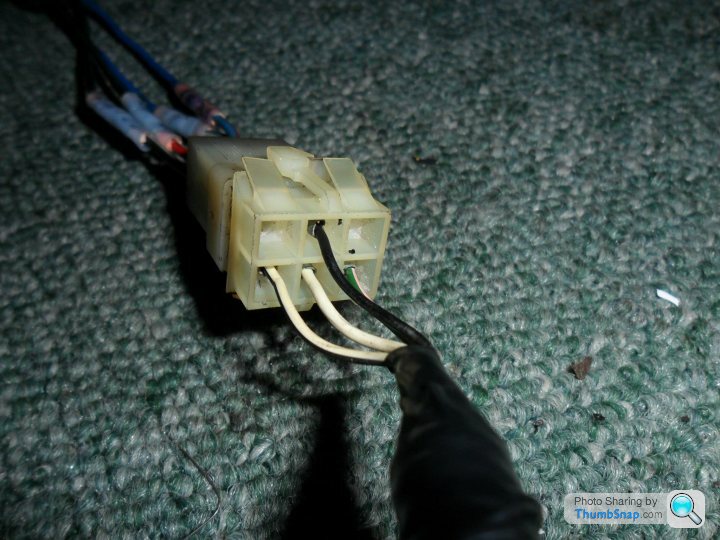
Front body loom connector
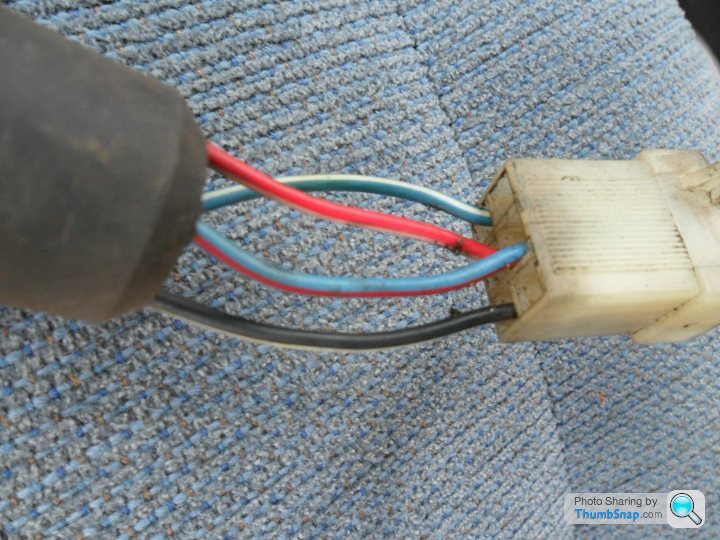
Original switch loom connector
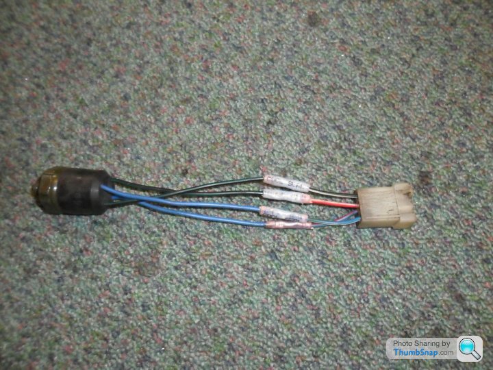
Modified switch
Images updated.
Here is the test rig
This identified the Blue/Red and Blue/White wires on the original switch as the low/high pressure switch as there was continuity at 25psi ish.
I then performed the same function test on the new switch and identified the low pressure side again (This was the black/green pair). I've assumed the matching wire colours are the 2 connections for each separate switch due to the continuity on the low side and the paired connectors (as it was received). I combined this with the original wire identification in the front body loom and have ended up with the following table.
| Switch Function | New Switch Wire Colour | Original Switch Wire Colour | Car Loom Colour |
|---|---|---|---|
| Low/High Pressure +ve | Black/Green | Blue/Red | Black |
| Low/High Pressure -ve | Black/Green | Blue/White | Green/Pink |
| Medium Pressure (fan control)+ve | Blue | Red/White | White/Pink |
| Medium Pressure (fan control)-ve | Blue | Black/White | White/Black |
First colour is the main wire colour, second colour is the tracer.
A few more pics from the work
Front body loom connector
Original switch loom connector
Modified switch
Edited by ridds on Tuesday 24th April 13:44
Images updated.
Edited by ridds on Sunday 9th July 19:25
Hi,
intersting this, I have a 94 Griffith 500 with the identical AC loom and trinary switch wire colours and connections. I too have purchased a new trinary switch (only as a spare though) but the wire colours and pin locations are differnt to the existing one.
However reading the thread you may or may not have made an error. My understanding of how the trinary switch works are the following. There are 2 switch circuits, one switch is a low pressure/high pressure cut out, i.e usually this switch is closed with a gassed system. The other switch is to activate the condensor fans, this switch activates at a mid pressure.
Lable on my new trinay switch (which has the same wire colours as yours) - Low pressure off 2.0 kg, High pressure off 28.0 kg, Mid pressure on 17.0 kg.
Now on my car loom, green/pink and black wires are connected to the fan switch in the trinary switch (blue/white, blue/red wires). I have bridge the green/pink & black wire this activated the condensor fans, I bridged the other 2 wires and this gave power to my compressor when AC switch turned on.
I see you have pressurised your new switch to get continuity on one circuit, however you mentioned a blue/green wire which does not make sense so promted this reply. Food for thought. I will be keen to see the outcome, as I too have no idea which wire colours connect to which.
Ozstyle
Ozstyle said:
Hi,
intersting this, I have a 94 Griffith 500 with the identical AC loom and trinary switch wire colours and connections. I too have purchased a new trinary switch (only as a spare though) but the wire colours and pin locations are differnt to the existing one.
However reading the thread you may or may not have made an error. My understanding of how the trinary switch works are the following. There are 2 switch circuits, one switch is a low pressure/high pressure cut out, i.e usually this switch is closed with a gassed system. The other switch is to activate the condensor fans, this switch activates at a mid pressure.
Lable on my new trinay switch (which has the same wire colours as yours) - Low pressure off 2.0 kg, High pressure off 28.0 kg, Mid pressure on 17.0 kg.
Now on my car loom, green/pink and black wires are connected to the fan switch in the trinary switch (blue/white, blue/red wires). I have bridge the green/pink & black wire this activated the condensor fans, I bridged the other 2 wires and this gave power to my compressor when AC switch turned on.
I see you have pressurised your new switch to get continuity on one circuit, however you mentioned a blue/green wire which does not make sense so promted this reply. Food for thought. I will be keen to see the outcome, as I too have no idea which wire colours connect to which.
Ozstyle
Yeah tweaked that now, the first sentence did say Blue/Green but should have been Blue/White.intersting this, I have a 94 Griffith 500 with the identical AC loom and trinary switch wire colours and connections. I too have purchased a new trinary switch (only as a spare though) but the wire colours and pin locations are differnt to the existing one.
However reading the thread you may or may not have made an error. My understanding of how the trinary switch works are the following. There are 2 switch circuits, one switch is a low pressure/high pressure cut out, i.e usually this switch is closed with a gassed system. The other switch is to activate the condensor fans, this switch activates at a mid pressure.
Lable on my new trinay switch (which has the same wire colours as yours) - Low pressure off 2.0 kg, High pressure off 28.0 kg, Mid pressure on 17.0 kg.
Now on my car loom, green/pink and black wires are connected to the fan switch in the trinary switch (blue/white, blue/red wires). I have bridge the green/pink & black wire this activated the condensor fans, I bridged the other 2 wires and this gave power to my compressor when AC switch turned on.
I see you have pressurised your new switch to get continuity on one circuit, however you mentioned a blue/green wire which does not make sense so promted this reply. Food for thought. I will be keen to see the outcome, as I too have no idea which wire colours connect to which.
Ozstyle
I thought the sensor actually has 2 "disconnected" switches. But there are 4 modes of operation as follows:
| Low/high Pressure Switch | Medium (Fan) Switch | System Function |
|---|---|---|
| 0 | 0 | No AC, pump off, fan off |
| 1 | 0 | System Active, pump on |
| 1 | 1 | System Active, pump on, fan on |
| 0 | 1 | No AC, Pump off, Fans active, |
Low switch only contacts between a certain, once the system pressure reaches either side of this window the pump will shut off. High Switch, this is purely the fan control, too high a pressure and the pump will shutdown.
Edited by ridds on Tuesday 24th April 13:42
Hi,
I don't really understand the 4 mode table. As you I thought the trinary switch had 2 basic switch circuits. I found a diagram on the internet and saved it a while ago, just dug it for a look. There are 3 internal switches, 2 switches on one circuit, 1 switch on the other circuit. The first circuit has a low pressure switch and a high pressure switch in line. The second circuit has a medium pressure switch. In the current unplugged situation, circuit 1 has the low pressure switch open, the high pressure switch closed. Circuit 2 medium pressure switch open - so no continuity across any terminals.
Since you got continuity at 25 psi (1.7 kg/cm2) by my reckoning your have continuity across the low pressure/high pressure cut off circuit. However, if I understand your table, you have connected that to the green/pink & black loom wires which is the fan switch (as activated by the medium pressure switch on the 2nd circuit).
Of course I could be wrong, knowing how TVR changed wiring colours and my TVR is a different model. However if I'm right, with your trinary switch on the gassed up AC system, your AC will not work as your AC logic will see the medium pressure switch in an open position - indicating too low or too high gas pressure. Might be worth some more investigation just to be happy.
Ozstyle
Posted this in anther thread, these are the pressure for the switch.
Male R134a trinary high & low pressure switch,

So, the only switch I could have activated was the Low pressure. Can't get my head round the pressures though as why would the high pressure need a second value? surely it will be activated and that's it? Or does it have a low threshold that it has to reach to then re-activate to allow the system pressure to reduce sufficiently?
Low activated above 29 PSI
Fan active between 185 and 227 PSI
High shuts it all down above 454 PSI and then re-activates once below 396 PSI
??????
This was one of the diagrams I found, which looking at it again confirms the Low/High and medium switches. However it is missing a wire! But this is because the Cerbera fan is activated by a switch to earth?

and looking at it again yes the table I drew up was certainly wrong (now tweaked for an obvious error and to correct the switch functions), although I think the wiring I have will function OK (this should be more apparent in the table now).
If the pair of wires that have continuity match on the 2 switches and then they are connected to the same location on the car then their function should be the same, which if it was the Low/High Pressure then it should still activate the pump correctly.
Looking at this diagram:
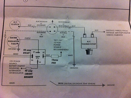
That confirms the same wire identity colours and function.
The other reference I found was this pdf document.
http://www.hotrodders.com/forum/attachment.php?att...
This was what prompted my 4 mode table. The first image in the document doesn't make it clear that NO contacts are made at the first stage, hence OFF.
Male R134a trinary high & low pressure switch,
| Function | Off or Open | On or Close | Off or Open | On or Close |
|---|---|---|---|---|
| Low Pressure Switch | 28 PSIG | 29 PSIG | 1.93 Bar | 1.99 Bar |
| Fan Switch | 185 PSIG | 227 PSIG | 12.7 Bar | 15.6 Bar |
| High Pressure Switch | 454 PSIG | 396 PSIG | 31.3 Bar | 25.4 Bar |
So, the only switch I could have activated was the Low pressure. Can't get my head round the pressures though as why would the high pressure need a second value? surely it will be activated and that's it? Or does it have a low threshold that it has to reach to then re-activate to allow the system pressure to reduce sufficiently?
Low activated above 29 PSI
Fan active between 185 and 227 PSI
High shuts it all down above 454 PSI and then re-activates once below 396 PSI
??????
This was one of the diagrams I found, which looking at it again confirms the Low/High and medium switches. However it is missing a wire! But this is because the Cerbera fan is activated by a switch to earth?
and looking at it again yes the table I drew up was certainly wrong (now tweaked for an obvious error and to correct the switch functions), although I think the wiring I have will function OK (this should be more apparent in the table now).
If the pair of wires that have continuity match on the 2 switches and then they are connected to the same location on the car then their function should be the same, which if it was the Low/High Pressure then it should still activate the pump correctly.
Looking at this diagram:
That confirms the same wire identity colours and function.
The other reference I found was this pdf document.
http://www.hotrodders.com/forum/attachment.php?att...
This was what prompted my 4 mode table. The first image in the document doesn't make it clear that NO contacts are made at the first stage, hence OFF.
Edited by ridds on Sunday 22 April 21:51
Hi,
yes that first diagram is similar to that I saw, agreed a wire missing but looks the same. The second diagram confirms the same colours as your new switch.
However you state the blue/white red/white gave you continuity at 25 psi which must be the low pressure switch (switch A on 1st diagram). On the second diagram blue/white red/white is the fan switch (switch C on 1st diagram)

Gassing Station | Cerbera | Top of Page | What's New | My Stuff