Discussion


Hi folks.
I have a Myford super 7 with a Brook,Crompton,Parkinson 550w single phase motor. I wired this in to a Dewhurst reversing switch as per the wiring diagram in the Myford manual, but when I tried to start the motor the RCD in the house tripped.
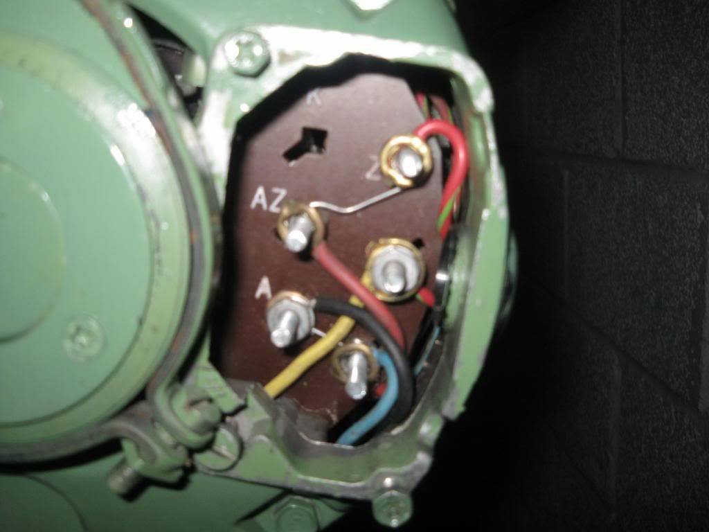
Upon firther inverstigation of the motor internal wiring, i see two fixed links between terminal AZ-Z and A-T. So, my question is are these links meant to be there? Or are they here because the previous owner had a 3 pin plug wired directly into the motor and the only way of starting it was by switching the wall socket on? I have attached a pic of the terminals for clarity.
I have a Myford super 7 with a Brook,Crompton,Parkinson 550w single phase motor. I wired this in to a Dewhurst reversing switch as per the wiring diagram in the Myford manual, but when I tried to start the motor the RCD in the house tripped.
Upon firther inverstigation of the motor internal wiring, i see two fixed links between terminal AZ-Z and A-T. So, my question is are these links meant to be there? Or are they here because the previous owner had a 3 pin plug wired directly into the motor and the only way of starting it was by switching the wall socket on? I have attached a pic of the terminals for clarity.
scottS3 said:
Hi folks.
I have a Myford super 7 with a Brook,Crompton,Parkinson 550w single phase motor. I wired this in to a Dewhurst reversing switch as per the wiring diagram in the Myford manual, but when I tried to start the motor the RCD in the house tripped.
Upon firther inverstigation of the motor internal wiring, i see two fixed links between terminal AZ-Z and A-T. So, my question is are these links meant to be there? Or are they here because the previous owner had a 3 pin plug wired directly into the motor and the only way of starting it was by switching the wall socket on? I have attached a pic of the terminals for clarity.
Two things, in order to reverse the motor you need to reverse the polarity of the capacitor in relation to the phase and neutral wires. These links, as have been said might be fixing this as itookes lime they join the incoming flex to the motor. Does you switch not replace these links?I have a Myford super 7 with a Brook,Crompton,Parkinson 550w single phase motor. I wired this in to a Dewhurst reversing switch as per the wiring diagram in the Myford manual, but when I tried to start the motor the RCD in the house tripped.
Upon firther inverstigation of the motor internal wiring, i see two fixed links between terminal AZ-Z and A-T. So, my question is are these links meant to be there? Or are they here because the previous owner had a 3 pin plug wired directly into the motor and the only way of starting it was by switching the wall socket on? I have attached a pic of the terminals for clarity.
Secondly, the rcd that tripped..is this the main CU rcd or is it actually the circuits mcb which is probably not motor rated? You will find mcbs come in b,c,d etc ratings...these allow for a greater start up current to be drawn from a motor load. You might need a c rated mcb..
Virgil, I can run the motor by connecting the single phase supply to the A and AZ terminals, so I dont think the breaker is the problem, I also run a pillar drill etc in the garage so I gues it rules the breaker out. I think you are right that the links need removed, and are replaced by the switch. In the manual this isnt mentioned so I never done it. I will try again.
http://www.google.co.uk/search?q=dewhurst+reversin...
reveals some drawings which mention removing the links, which make sense given they are intended for hard wiring the direction.
reveals some drawings which mention removing the links, which make sense given they are intended for hard wiring the direction.
Gassing Station | Homes, Gardens and DIY | Top of Page | What's New | My Stuff