Bird on a wire - the rewire begins
Discussion


magpies said:
phillpot said:
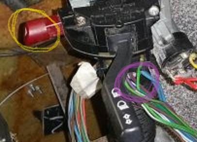
Horn push should be on the left hand (indicator) stalk ?
It ain't on mineLooking back at your photo, correct switch has a square hazard button and those purple wires just visible should be for the horn.
Edited by phillpot on Sunday 25th November 09:24
phillpot said:
magpies said:
phillpot said:
Horn push should be on the left hand (indicator) stalk ?
It ain't on mineLooking back at your photo, correct switch has a square hazard button and those purple wires just visible should be for the horn.
Edited by phillpot on Sunday 25th November 09:24
Hi Penny
is it ok to have the relay activation coil feed fuses fed from the 'switched live' via the Ign relay and have the 'power' feeds to the relays fed from 'permanent live' fuses or should both the power and activation feeds be via the 'switched live' fuses?
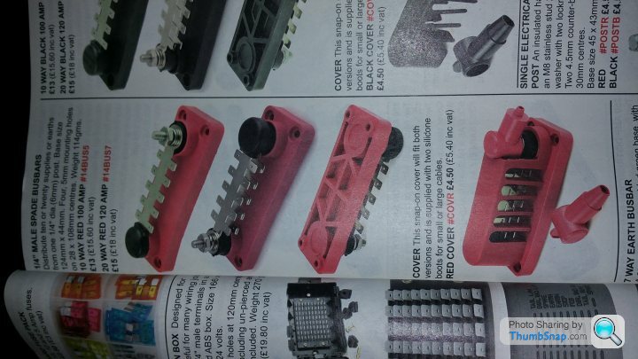
I will be purchasing busbar feeds for both perm and switched fuse banks.
Looks like I'll be needing approx. 26 fuses, the bus bars come in either 10 or 20 spade outlets. So will need three - 2 perm/1 switched or 1 perm/2 switched
with a few spare. Also need fuses not fed from the battery (Main/Dip/Flash/Rear Fog)
or am I reading too much into this?
is it ok to have the relay activation coil feed fuses fed from the 'switched live' via the Ign relay and have the 'power' feeds to the relays fed from 'permanent live' fuses or should both the power and activation feeds be via the 'switched live' fuses?
I will be purchasing busbar feeds for both perm and switched fuse banks.
Looks like I'll be needing approx. 26 fuses, the bus bars come in either 10 or 20 spade outlets. So will need three - 2 perm/1 switched or 1 perm/2 switched
with a few spare. Also need fuses not fed from the battery (Main/Dip/Flash/Rear Fog)
or am I reading too much into this?
magpies said:
Hi Penny
is it ok to have the relay activation coil feed fuses fed from the 'switched live' via the Ign relay and have the 'power' feeds to the relays fed from 'permanent live' fuses or should both the power and activation feeds be via the 'switched live' fuses?
I will be purchasing busbar feeds for both perm and switched fuse banks.
Looks like I'll be needing approx. 26 fuses, the bus bars come in either 10 or 20 spade outlets. So will need three - 2 perm/1 switched or 1 perm/2 switched
with a few spare. Also need fuses not fed from the battery (Main/Dip/Flash/Rear Fog)
or am I reading too much into this?
No you're not reading too much into it, it's all good thinkingis it ok to have the relay activation coil feed fuses fed from the 'switched live' via the Ign relay and have the 'power' feeds to the relays fed from 'permanent live' fuses or should both the power and activation feeds be via the 'switched live' fuses?
I will be purchasing busbar feeds for both perm and switched fuse banks.
Looks like I'll be needing approx. 26 fuses, the bus bars come in either 10 or 20 spade outlets. So will need three - 2 perm/1 switched or 1 perm/2 switched
with a few spare. Also need fuses not fed from the battery (Main/Dip/Flash/Rear Fog)
or am I reading too much into this?
Battery supply to relay terminal 30 is the best method
Switched supply to relay coil terminal 86 can be whatever you choose
Fuse the relay outputs not the inputs. You won't need to fuse the relay supply If your battery is very close to the fusebox
If the battery is below the fusebox and relays you will have to have it in a box so that it doesn't gas upwards and end up corroding everything, perhaps you're using a sealed battery or one with a venting tube that vents out of the car through the floor, or maybe a gell type????
I can easily post you a fusing/relay wiring method
You won't be able to fuse the circuits correctly if you use bus-bar fuseboxes, this is why I earlier posted you a link to the correct type of fusebox
https://www.carbuildersolutions.com/uk/12-way-blad...
https://www.carbuildersolutions.com/uk/12-way-blad...
v8s4me said:
If the busbar in the fuse box is the common earth, like this one what is the issue?
The proposed busbars are completely separatand before the fusebox. They are basically to distribute the large battery cable down to multiple spade connectors then these wired to the individual circuit fuses.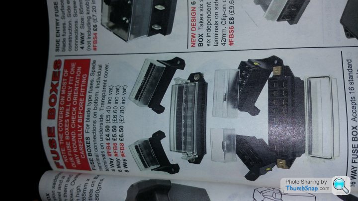
Penelope Stopit said:
No you're not reading too much into it, it's all good thinking
Battery supply to relay terminal 30 is the best method
Switched supply to relay coil terminal 86 can be whatever you choose
Fuse the relay outputs not the inputs. You won't need to fuse the relay supply If your battery is very close to the fusebox
If the battery is below the fusebox and relays you will have to have it in a box so that it doesn't gas upwards and end up corroding everything, perhaps you're using a sealed battery or one with a venting tube that vents out of the car through the floor, or maybe a gell type????
I can easily post you a fusing/relay wiring method
Yes a fuse / relay wiring method will be good. I've emailed you.Battery supply to relay terminal 30 is the best method
Switched supply to relay coil terminal 86 can be whatever you choose
Fuse the relay outputs not the inputs. You won't need to fuse the relay supply If your battery is very close to the fusebox
If the battery is below the fusebox and relays you will have to have it in a box so that it doesn't gas upwards and end up corroding everything, perhaps you're using a sealed battery or one with a venting tube that vents out of the car through the floor, or maybe a gell type????
I can easily post you a fusing/relay wiring method
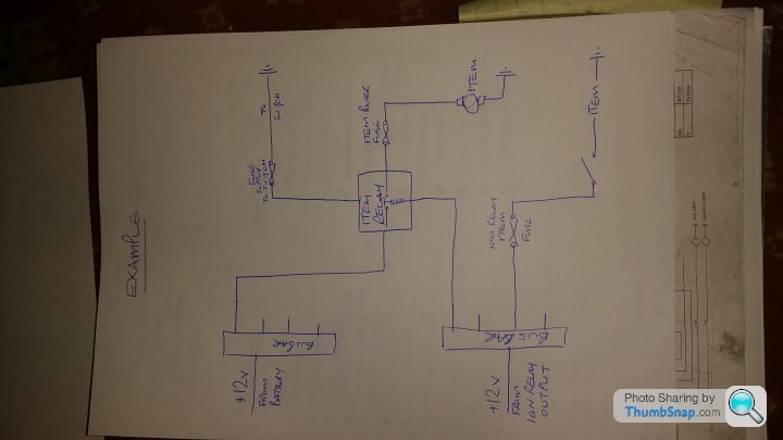 |https://thumbsnap.com/HKFCjhHM[/url]
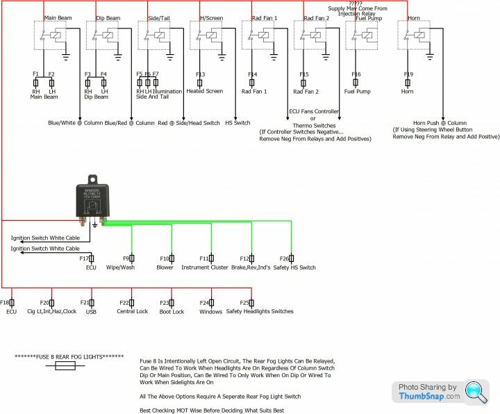
Take a look, see what you think.......
Fuse 1 RH Main (Supplied From Main Beam Relay)
Fuse 2 LH Main (Supplied From Main Beam Relay)
Fuse 3 RH Dip (Supplied From Dip Beam Relay)
Fuse 4 LH Dip (Supplied From Dip Beam Relay)
Fuse 5 RH Side/Tail/Number Plate (Supplied From Side Light Relay)
Fuse 6 LH Side/Tail/Number Plate (Supplied From Side Light Relay)
Fuse 7 Illumination (Supplied From Side Light Relay)
Fuse 8 Rear Fog Lights (Supplied From Fog Light Switch That's Supplied From Side Light Relay or Dip Beam Relay)
Fuse 9 Wipers/Washer (Ignition Supplied From Main Ignition Relay To Wiper Switch And Motor For Park)
Fuse 10 Blower Motor (Ignition Supplied From Main Ignition Relay To Blower Motor or Blower Switch)
Fuse 11 Instrument Cluster (Ignition Supplied From Main Ignition Relay)
Fuse 12 Brake/Reverse/Indicator Lights (Ignition Supplied From Main Ignition Relay To Switches And Hazard Switch)
Fuse 13 Heated Screen (Supplied From Heated Screen Relay)
Fuse 14 Radiator Fan 1 (Supplied By Ignition And Sensor Controlled Relay Fan 1)
Fuse 15 Radiator Fan 2 (Supplied By Ignition And Sensor Controlled Relay Fan 2)
Fuse 16 Fuel Pump (ECU Switched Supplied From Fuel Pump Relay)
Fuse 17 ECU (Ignition Supplied From Ignition Switch)
Fuse 18 ECU (Bat +ive)
Fuse 19 Horn (Bat +ive Supplied From Horn Relay)
Fuse 20 Cigarette Lighter,Interior Light,Hazard Flasher, Clock, (Bat +ive)
Fuse 21 USB (Bat +ive)
Fuse 22 Central Locking (Bat +ive)
Fuse 23 Boot Release (Bat +ive)
Fuse 24 Windows (Bat +ive) or (Ignition) And (Perhaps A Relay)?????
Fuse 25 Safety Fuse (Bat +ive To Side/Headlight Switch And Main Beam Flash Supply At Column Switch)
Fuse 26 Safety Fuse (Ignition Supplied From Main Ignition Relay To Heated Screen Switch)
1 X 100 AMP - Ignition Relay
Relay 1 - Main Beam
Relay 2 - Dip Beam
Relay 3 - Side/Tail/Illumination
Relay 4 - Heated Screen Relay
Relay 5 - Radiator Fan 1
Relay 6 - Radiator Fan 2
Relay 7 - Fuel Pump
Relay 8 - Horn
Relay 9 - Windows (See Fuse 24)?????
Relay 10 - Flasher Unit 2 And 4 x 21 Watts (Perhaps + 2 x 5 Watts For Side Repeaters)
- ******Fuel Injection Relay********???????
Edited by Penelope Stopit on Thursday 29th November 16:56

Looks good Stoppedit 
minor comments / probable changes to keep the totals down to that I've alreadypurchased
I'd supply the dash illumination from a side light fuse - almost all LED
probably not worth fitting relay to side/illumination as very little current draw and switch is designed for no relay
Rad Fans - agaon I'd keep with original Sierra Cossy design of only one fuse and relay
Car does not have electric windows
probably require a boot solenoid relay
Fogs supplied by side/head switch so not on with sidelights
don't know yet if injectors needs a fuse/relay but will check with Jag wiring diagram
If I do require more fuses / relays I will obtain
Once again cheers Penelope
magpies said:
Looks good Stoppedit
minor comments / probable changes to keep the totals down to that I've alreadypurchased
I'd supply the dash illumination from a side light fuse - almost all LED
probably not worth fitting relay to side/illumination as very little current draw and switch is designed for no relay
Rad Fans - agaon I'd keep with original Sierra Cossy design of only one fuse and relay
Car does not have electric windows
probably require a boot solenoid relay
Fogs supplied by side/head switch so not on with sidelights
don't know yet if injectors needs a fuse/relay but will check with Jag wiring diagram
If I do require more fuses / relays I will obtain
Once again cheers Penelope
Glad to be of helpminor comments / probable changes to keep the totals down to that I've alreadypurchased
I'd supply the dash illumination from a side light fuse - almost all LED
probably not worth fitting relay to side/illumination as very little current draw and switch is designed for no relay
Rad Fans - agaon I'd keep with original Sierra Cossy design of only one fuse and relay
Car does not have electric windows
probably require a boot solenoid relay
Fogs supplied by side/head switch so not on with sidelights
don't know yet if injectors needs a fuse/relay but will check with Jag wiring diagram
If I do require more fuses / relays I will obtain
Once again cheers Penelope
Tomorrow I will ditch....
Side Light Relay & Illumination Fuses
Rad Fan Circuit 2
Windows Fuse
- *And Add***....
To Diagram****Boot Release Relay**** Needs to be fitted in the boot somewhere as this method uses least wiring, the relay only needs the fused supply from front to back
I don't know what setup you have at present for switching the boot release relay, if you are only operating it from the back you could run a cable from front to back and have a dash button
Let me know what you want me to show for the boot release
The thing Is I've started so I'll finish.....all being well when the jobs completed you will have a correct diagram of the finished wiring for the relays and fuses
I hope you now see the benefits of fusing the outputs from the relays rather than the inputs to the relays
Cheers, time for a beer
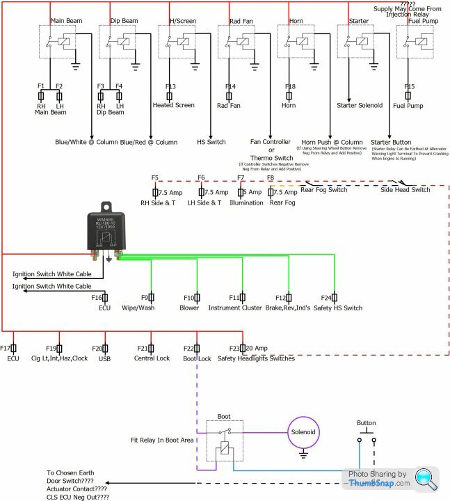
Here you go now updated, I forgot about the starter relay in the above diagram and have now added it
Fuse 1 RH Main (Supplied From Main Beam Relay)
Fuse 2 LH Main (Supplied From Main Beam Relay)
Fuse 3 RH Dip (Supplied From Dip Beam Relay)
Fuse 4 LH Dip (Supplied From Dip Beam Relay)
Fuse 5 RH Side/Tail/Number Plate
Fuse 6 LH Side/Tail/Number Plate
Fuse 7 Illumination
Fuse 8 Rear Fog Lights (Supplied From Fog Light Switch That's Supplied From Side/Head Switch)
Fuse 9 Wipers/Washer (Ignition Supplied From Main Ignition Relay To Wiper Switch And Motor For Park)
Fuse 10 Blower Motor (Ignition Supplied From Main Ignition Relay To Blower Motor or Blower Switch)
Fuse 11 Instrument Cluster (Ignition Supplied From Main Ignition Relay)
Fuse 12 Brake/Reverse/Indicator Lights (Ignition Supplied From Main Ignition Relay To Switches And Hazard Switch)
Fuse 13 Heated Screen (Supplied From Heated Screen Relay)
Fuse 14 Radiator Fan (Supplied By Ignition And Sensor Controlled Relay)
Fuse 15 Fuel Pump (ECU Switched Supplied From Fuel Pump Relay)
Fuse 16 ECU (Ignition Supplied From Ignition Switch)
Fuse 17 ECU (Bat +ive)
Fuse 18 Horn (Bat +ive Supplied From Horn Relay)
Fuse 19 Cigarette Lighter,Interior Light,Hazard Flasher, Clock, (Bat +ive)
Fuse 20 USB (Bat +ive)
Fuse 21 Central Locking (Bat +ive)
Fuse 22 Boot Release (Bat +ive)
Fuse 23 Safety Fuse (Bat +ive To Side/Headlight Switch And Main Beam Flash Supply At Column Switch)
Fuse 24 Safety Fuse (Ignition Supplied From Main Ignition Relay To Heated Screen Switch)
1 X 100 AMP - Ignition Relay
Relay 1 - Main Beam
Relay 2 - Dip Beam
Relay 3 - Heated Screen Relay
Relay 4 - Radiator Fan
Relay 5 - Horn
Relay 6 - Starter
Relay 7 - Fuel Pump
Relay 8 - Boot
Relay 9 - Flasher Unit 2 And 4 x 21 Watts (Perhaps + 2 x 5 Watts For Side Repeaters)
- ******Fuel Injection Relay********???????
Gassing Station | S Series | Top of Page | What's New | My Stuff